Lens barrel

a barrel and lens technology, applied in the field of lenses barrels, can solve the problems of poor operation, unintentional touching and moving, and wrong operation of instruction-type focus rings

Active Publication Date: 2007-06-28
FUJIFILM CORP
View PDF16 Cites 39 Cited by
  • Summary
  • Abstract
  • Description
  • Claims
  • Application Information

AI Technical Summary

Benefits of technology

[0017] According to the lens barrel of the present invention, when the two focus rings of the relative position instruction type and the absolute position instruction type are provided at the lens barrel, the nonconformity that the user erroneously operates the focus ring of the instruction type not intended to be operated can be prevented.

Problems solved by technology

When these professional photographers use the above relative position instructing type focus ring, they can not recognize that the focus lens has reached the close-up end or infinite end by the operation feeling of the focus ring, and there is nonconformity that the operability is poor.
However, if there are different instruction types of focus rings in one lens barrel, there is a fear of wrong operation of an instruction type focus ring not intended to be operated by the user taken it as the other focus ring or unintentional touching and moving of it.

Method used


Image

  • Lens barrel
  • Lens barrel
  • Lens barrel

Examples


Embodiment Construction

[0029] The best mode for carrying out the lens barrel according to the present invention will be described below based on the attached drawings.

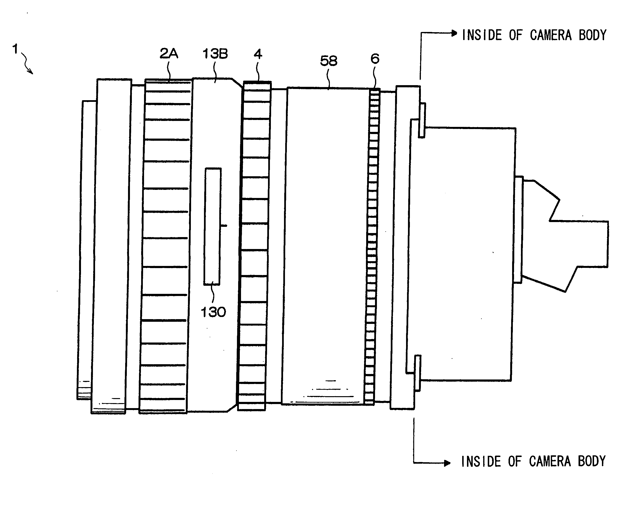
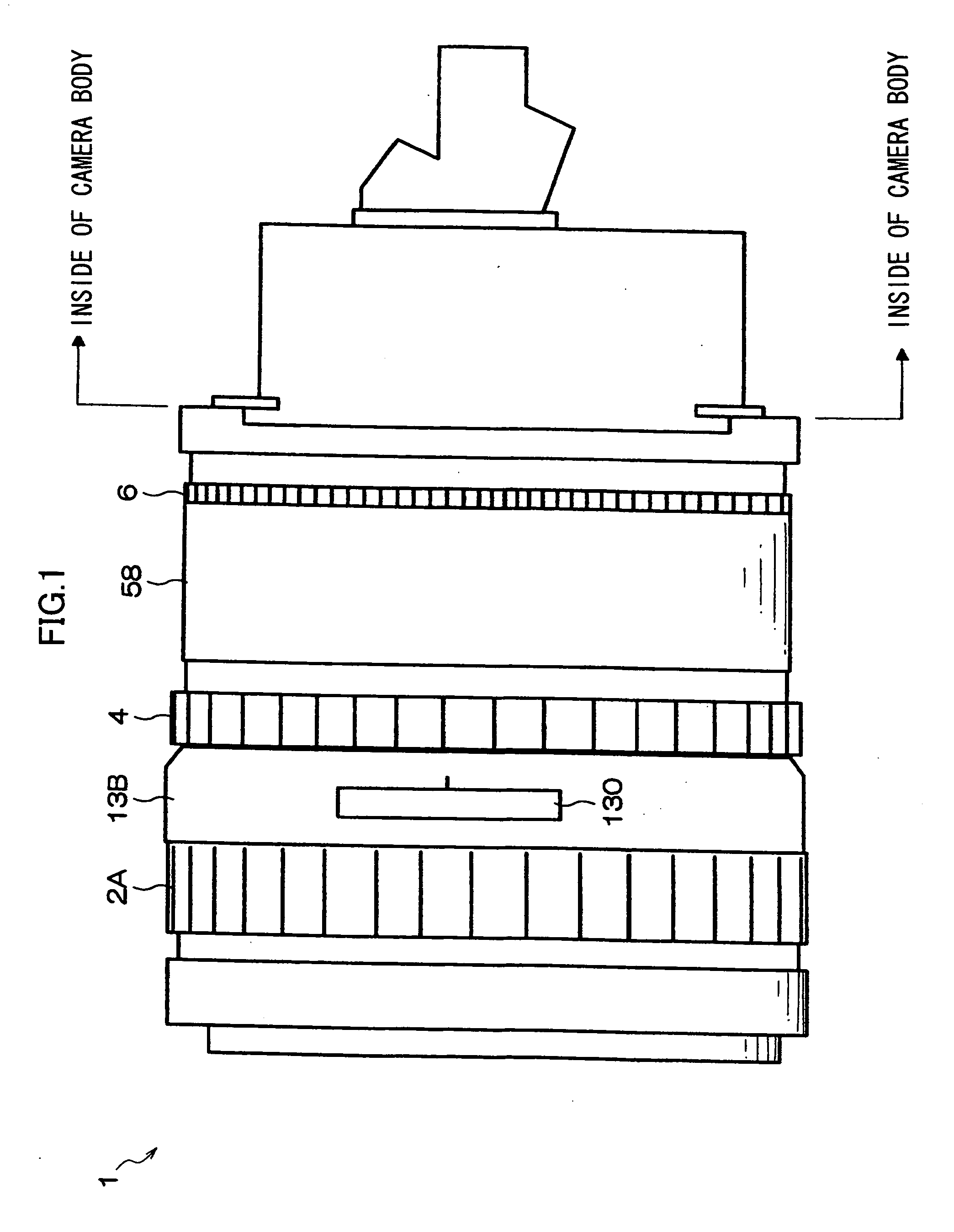
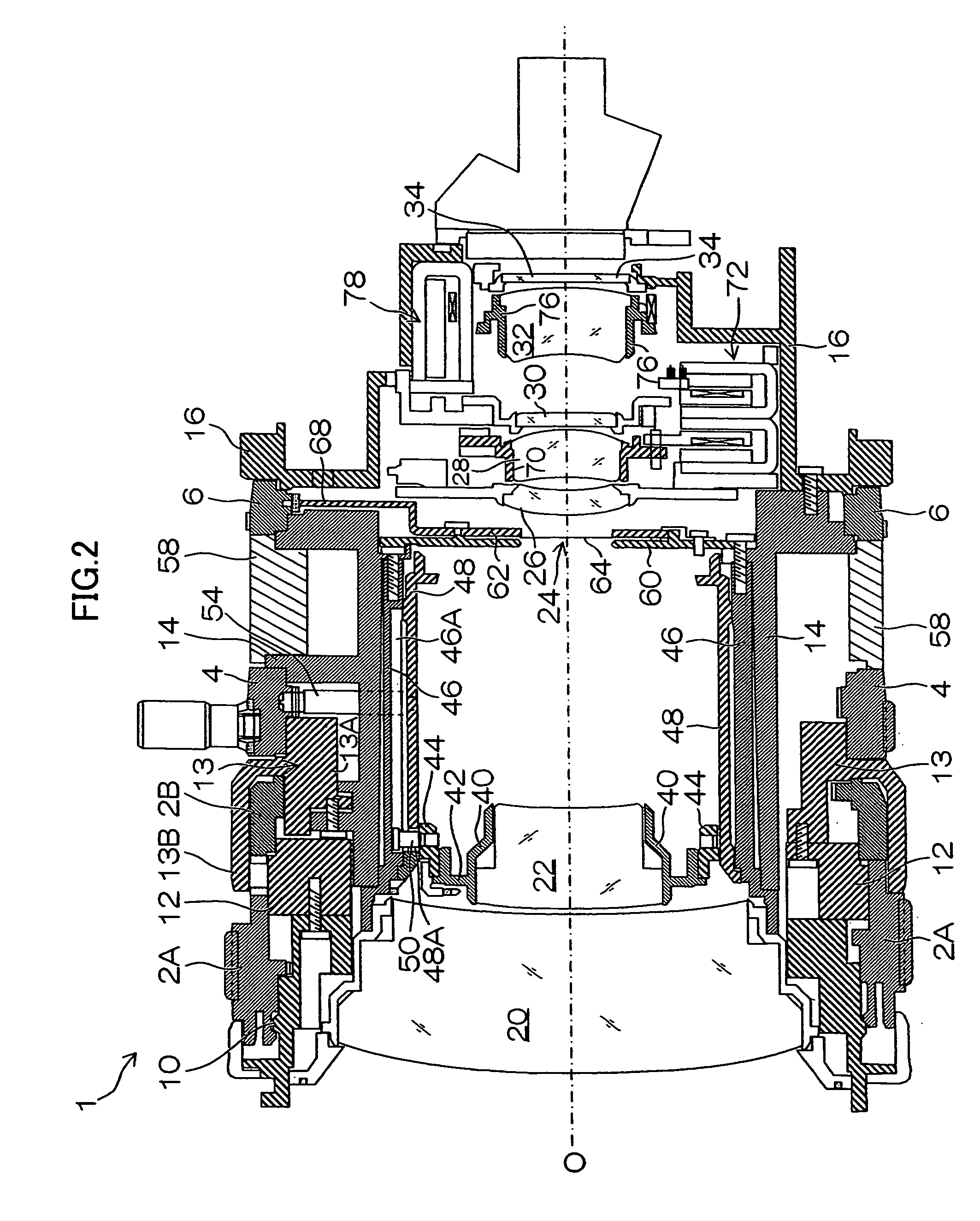
[0030]FIGS. 1 and 2 show a side view and a side sectional view, respectively, showing a lens barrel in a rear-focus type variable focal distance photographing lens applied to a video camera for consumers, an ENG camera for TV broadcasting, a monitoring camera and the like, for example, to which the present invention is applied. In these figures, a lens barrel used mainly in the video camera for consumers is shown, and an optical block such as color separation prism attached on a camera body with interchangeable lenses is integrally mounted at a rear end of a lens barrel 1.

[0031] In FIG. 1, the lens barrel 1 is constructed in the substantially cylindrical shape and it is fixed to an enclosure of a camera body in the state where a part of the rear end side is inserted into the enclosure of the camera body, not shown. Rotatable operation ring...


PUM


Abstract

The present invention provides a lens barrel comprising: a first focus ring which is used for either one of instruction types of focus operation of a relative position instruction type focus operation for moving a position of the focus lens for focus control with respect to an optical axis direction in a relative positional relation to a rotation position of the focus ring and an absolute position instruction type focus operation for moving it in an absolute positional relation; a second focus ring which is used for the focus operation of the instruction type different from that of the first focus ring between the relative position instruction type focus operation and the absolute position instruction type focus operation; a support device which slidably supports the first focus ring in the optical axis direction; a connecting device which brings the first focus ring and the second focus ring from an unconnected state into a connected state when the first focus ring slidably supported by the support device is slid from a first position to a second position; and a cover member covering the outer circumference portion of the second focus ring.

Description

BACKGROUND OF THE INVENTION [0001] 1. Field of the Invention [0002] The present invention relates to a lens barrel and particularly to a lens barrel provided with a focus ring for focusing operation and a mechanism for driving the focus lens by a motor according to a rotation position of the focus ring by electrically detecting the rotation position of the focus ring. [0003] 2. Description of the Related Art [0004] A consumer video camera in general has an automatic focus function so that focusing can be controlled by switching between automatic focus and manual focus. Thus, a lens for focus control (focus lens) is driven by a motor, and a manual focus is carried out by electrically detecting the rotation position of a focus ring provided rotatably at a lens barrel by a position sensor, for example, and by moving the focus lens by the motor according to the detected rotation position. And the focus ring and the focus lens are so constructed that they are not mechanically interlocked...

Claims


Application Information

Patent Timeline
Patent Type & Authority Applications(United States)
IPC IPC(8): G02B7/04
CPCG02B7/102
Inventor MORI, YOSHITAKA
Owner FUJIFILM CORP
Why Eureka
Try Eureka