
Lateral maneuverability map for a moving object and method for generation thereof

Active Publication Date: 2007-06-28
BEIJING VOYAGER TECH CO LTD
View PDF2 Cites 38 Cited by
  • Summary
  • Abstract
  • Description
  • Claims
  • Application Information

AI Technical Summary

Benefits of technology

[0011] Advantageously, when the vehicle is an aircraft, the lateral maneuverability map is added, as a transparent overlay, to a map delivered by a TAWS system for preventing the risk of collision with the ground.

Problems solved by technology

However, the known navigational aid maps indicating the nonnegotiable parts or parts that are prohibited from being negotiated as obstacles to be circumvented, give no information about the extent of the areas adjacent to the obstacles in which the vehicle has little freedom of movement in the short term owing to the proximity of an obstacle to be circumvented.

Method used


Image

  • Lateral maneuverability map for a moving object and method for generation thereof
  • Lateral maneuverability map for a moving object and method for generation thereof
  • Lateral maneuverability map for a moving object and method for generation thereof

Examples


Embodiment Construction

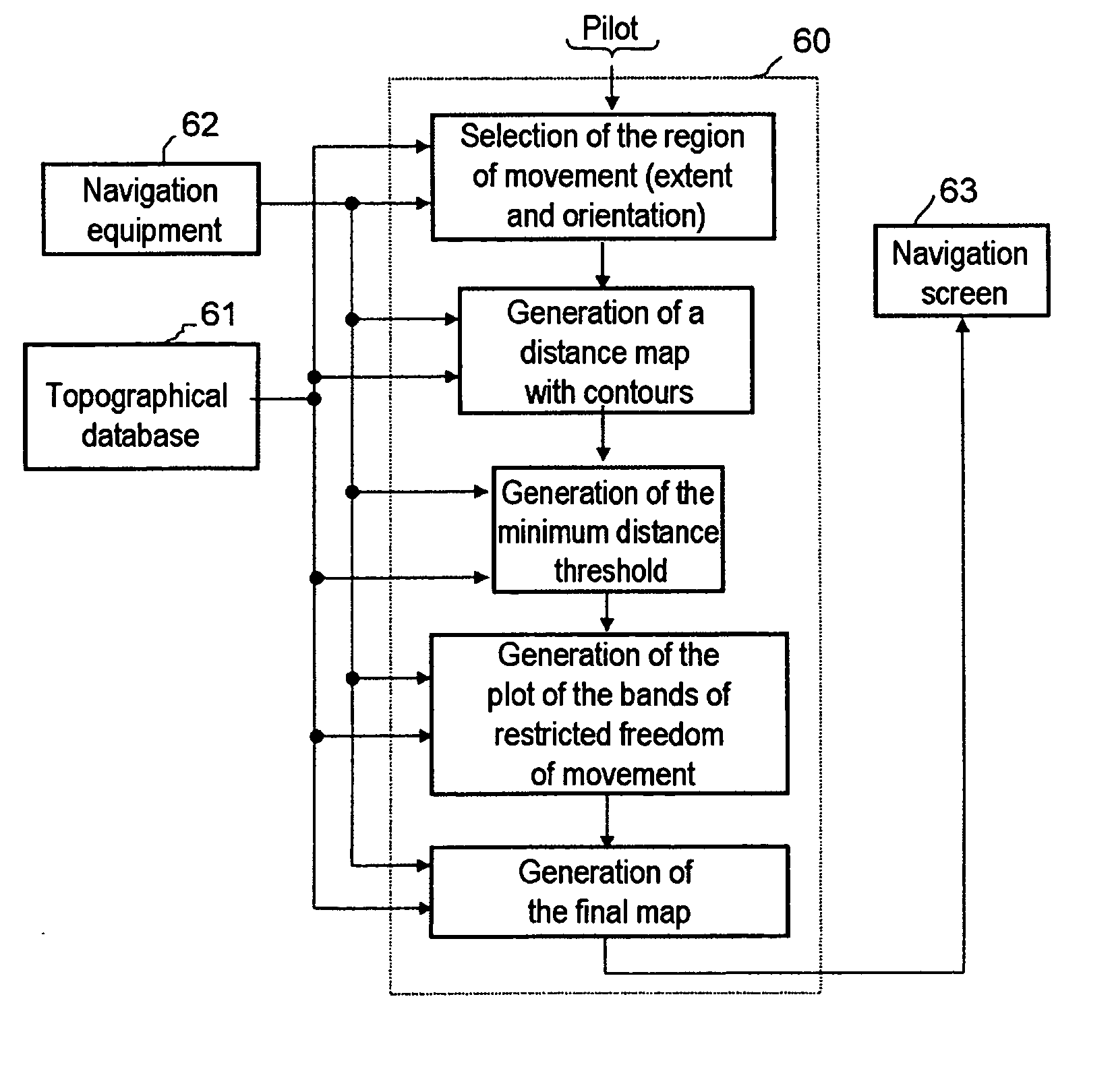
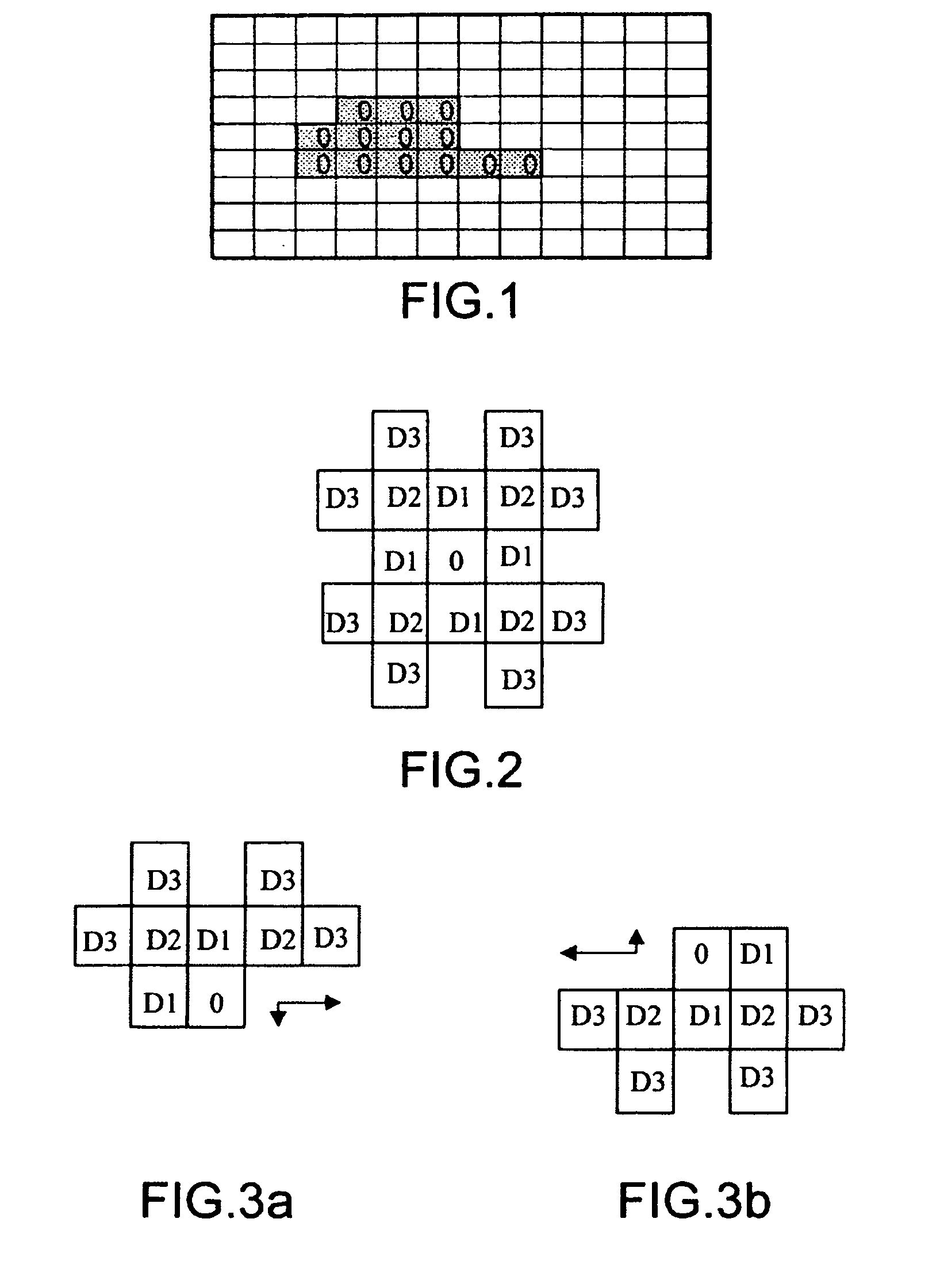
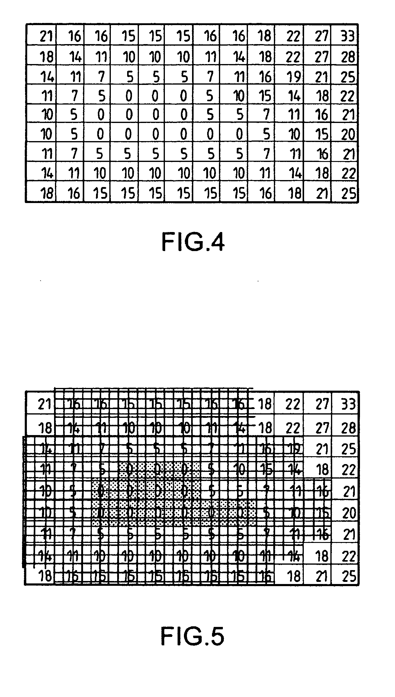
[0053] As shown in FIG. 1, the generation of the lateral maneuverability map starts by the construction of a distance map initiated by the authoritative assignment of a zero-distance estimate to the cells of the mapped area resulting from the adopted subdivision for the database of terrain elevations, which cells belong to those parts of the area of movement that are considered as having to be circumvented.

[0054] The selection of these cells results from various considerations, which will not be explained in detail here as they do not form part of the invention. For an aircraft, these may be cells corresponding to reliefs close to or above the altitude setpoint of its flight plan or to a prediction of the altitude of the aircraft in the short or medium term based on its actual flight parameters. They may also be totally prohibited areas of overflight or below a minimum altitude above the altitude setpoint of the aircraft's flight plan or a prediction of its altitude in the short or...


PUM


Abstract

This lateral maneuverability map shows the area of movement of a vehicle with the contours of the regions of complete freedom of lateral movement. It is generated from a distance map listing the distances of the points of its regions that can be negotiated by the vehicle to the regions to be circumvented. It may show the area of movement of the vehicle in the form of a subdivision into at least three types of region, namely a first type corresponding to regions to be circumvented, a second type corresponding to bands surrounding the regions to be circumvented and having the width of a maneuvering space arbitrarily considered as necessary for free lateral movement of the vehicle, and a third type of region corresponding to regions of free lateral movement. In the case of an aircraft, said map may be superimposed on the map of a TAWS system in order to specify to the pilot if he has complete freedom of lateral movement or not.

Description

CROSS-REFERENCE TO RELATED APPLICATIONS [0001] The present Application is based on International Application No. PCT / EP2004 / 053175, filed on Nov. 30, 2004, which in turn corresponds to FR 03 / 15020 filed on Dec. 19, 2003, and priority is hereby claimed under 35 USC §119 based on these applications. Each of these applications are hereby incorporated by reference in their entirety into the present application.BACKGROUND OF THE INVENTION [0002] 1. Field of the Invention [0003] The invention relates to a navigational aid for a vehicle subject to maneuverability and path constraints, such as an aircraft flying over territory having inhibited areas of overflight below a certain floor or reliefs and obstacles to be circumvented as they are close to or above its flight altitude. [0004] 2. Description of the Related Art [0005] Various systems have been developed for warning the crew of an aircraft of a risk of collision with the ground. Some of these, such as terrain awareness and warning sys...

Claims


Application Information

Patent Timeline
IPC IPC(8): G05D1/00G01C21/00G09B29/10
CPCG09B29/10G08G5/0021G08G5/0052G08G5/0086G08G5/045
Inventor BITAR, ELIASMARTY, NICOLAS
Owner BEIJING VOYAGER TECH CO LTD
Learn More