Manufacturing method of rubber member for tire

a rubber member and tire technology, applied in the field of strip wind construction method of forming a rubber member for a tire, can solve the problems of increasing risk, reducing productivity, and generating air reservoirs, and achieve the effect of effectively transmitting the pressing force and high precision

Inactive Publication Date: 2007-07-05
SUMITOMO RUBBER IND LTD
View PDF5 Cites 2 Cited by
  • Summary
  • Abstract
  • Description
  • Claims
  • Application Information

AI Technical Summary

Benefits of technology

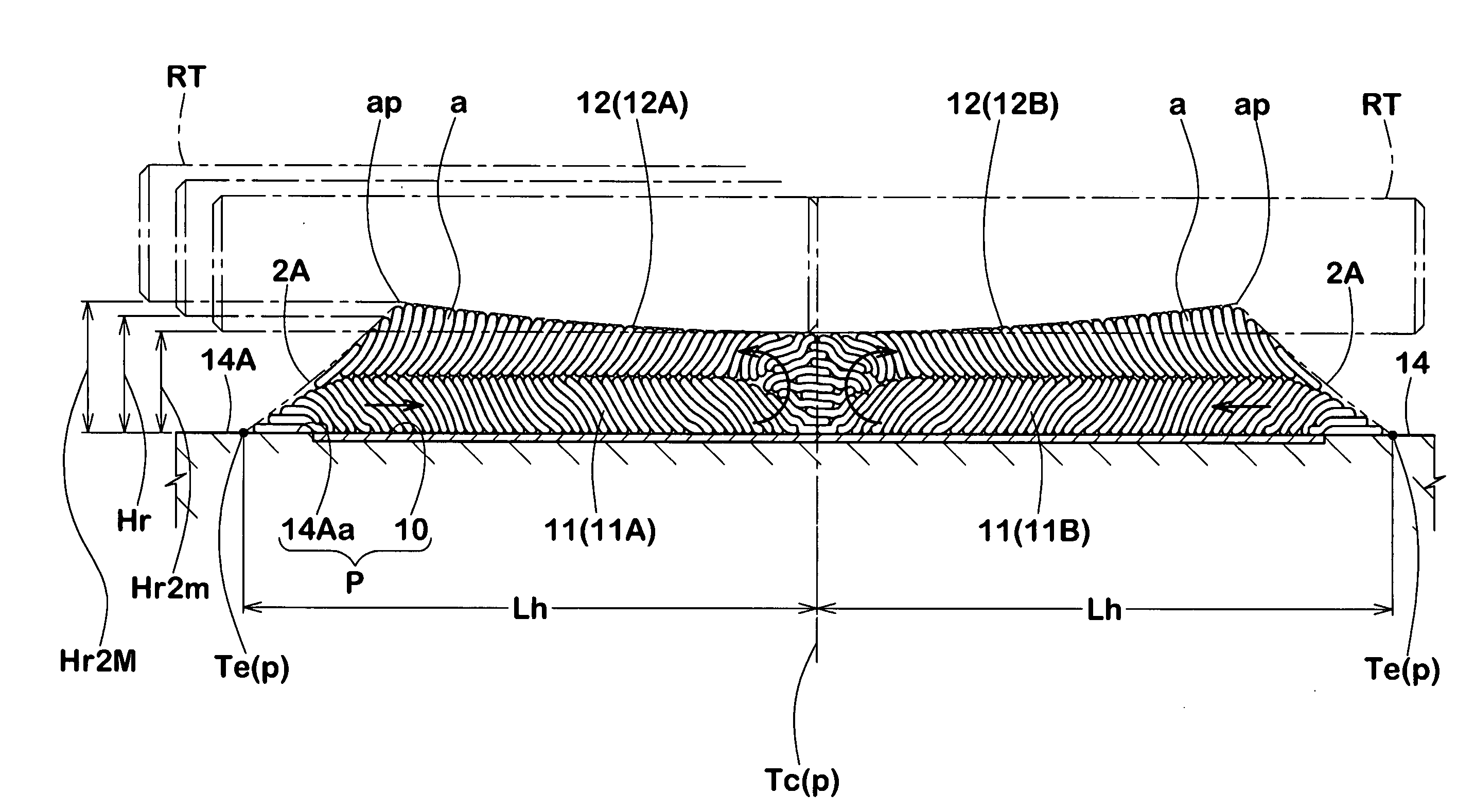
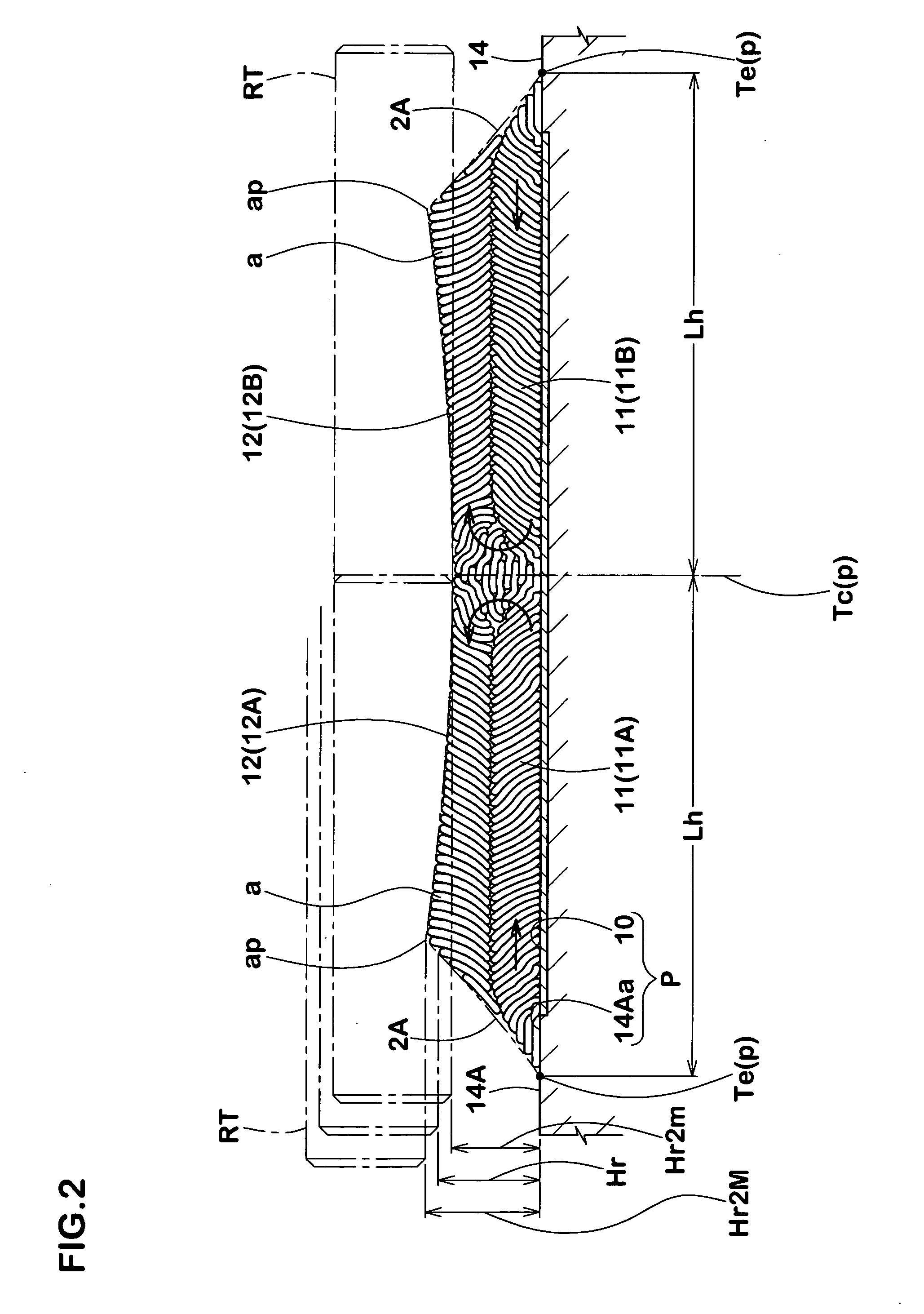
[0010] As a result of making a study of the formation of the rubber member with a high precision and with no air reservoir in accordance with the STW method, there is conceived that it is preferable to execute a pressing as uniform as possible and set the thickness about a half height of each of the rubber members G without making the thickness too large, in order to obtain a preferable rubber member. Accordingly, it is possible to effectively transmit the pressing force by the pressing roller RT to an entire thickness of each of the layers. Further, there is conceived that it is preferable to spirally wind an entire length by dividing in a length direction in place of continuously winding the entire length in the tire axial direction.

Problems solved by technology

However, in the STW method mentioned above, since the rubber strip is spirally wound, an air reservoir tends to be generated due to a step in a side edge of the rubber strip or the like.
There is an increased risk that the air reservoir is generated between a wound body such as a drum or the like, and a rubber layer spirally wound in an outer side in a radial direction thereof, or between the inner and outer rubber layers in the radial direction in comparison with the conventional one mouth method.
However, it becomes necessary to hold specialized mouth pieces for the extruding machine, and a productivity tends to be lowered.

Method used


Image

  • Manufacturing method of rubber member for tire
  • Manufacturing method of rubber member for tire
  • Manufacturing method of rubber member for tire

Examples


examples

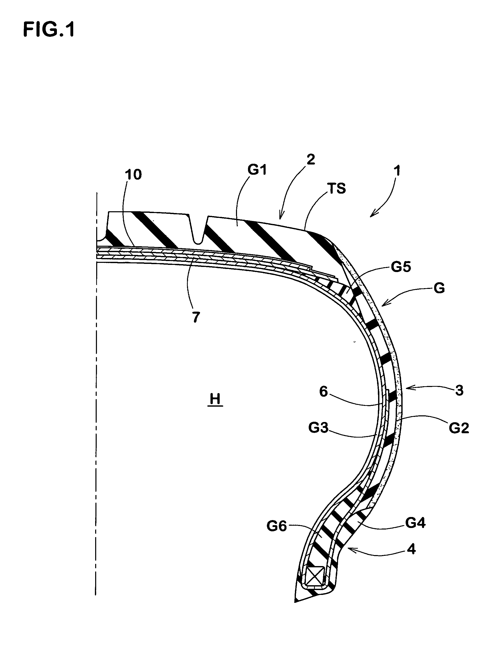
[0055] There is manufactured a tread rubber G1 of a pneumatic radial tire for a passenger car on the basis of a tire size of 215 / 45ZR17 and a specification shown in Table 1. A test is executed about a performance thereof. In this case, a rubber strip is set to be identical. Results thereof are shown in Table 1. In the tested specification, FIGS. 2 and 3 are set to an example 1, FIGS. 5 and 6 are set to an example 2, FIG. 9 is set to a comparative example 1, and FIG. 10 is set to a comparative example 2.

TABLE 1ExampleExampleComparativeComparative12Example 1Example 2Specificationand 3and 6Rubber strip15 × 115 × 130 × 130 × 1width × thick-ness (mm)Uniformity52535957RFV (N)

[0056] Twenty tires are manufactured for each of the tires, and a uniformity is measured. The uniformity is measured as a radial force variation (RFV) on the basis of a uniformity test condition of JASO C607:2000. An evaluated speed is set to 10 km / h. Results are expressed by an average (N) of twenty tires, and the ...


PUM

PropertyMeasurementUnit
widthaaaaaaaaaa
widthaaaaaaaaaa
thicknessaaaaaaaaaa

Abstract

In a strip wind construction method, the invention provides a manufacturing method of a rubber member for a tire which can reduce an air remnant in a rubber member. A rubber member has an inside first layer formed by spirally winding a rubber strip from a starting point corresponding to any one of reference positions of a center position of a wound body and a side edge to the other reference position in an axial direction in a half region between the center position and an outer edge in a tire axial direction of a winding region, and a second layer formed by folding back from a starting point corresponding to the other reference position to the other in an axial direction, and the reference position corresponding to the starting pint is set to a line-symmetrical position around the center position.

Description

BACKGROUND OF THE INVENTION [0001] 1. Field of the Invention [0002] The present invention relates to a strip wind construction method of forming a rubber member for a tire by spirally winding a rubber strip, and more particularly to a manufacturing method of a rubber member for a tire which can reduce a air remnant in the rubber member. [0003] 2. Description of the Related Art [0004] There has been considered to form a rubber member in each of positions of tire, such as a tread rubber, a side wall rubber or the like by spirally winding a rubber strip made of a material corresponding to a demand characteristic of the rubber member. By the strip wind construction method, a mouth piece of a nozzle and a labor hour of a management can be reduced in comparison with an conventional extrusion molding method of continuously extruding from a mouth piece in a predetermined finish cross sectional shape. Further, it is possible to use a compact rubber extruding machine, and it is possible to ac...

Claims


Application Information

Patent Timeline
Patent Type & Authority Applications(United States)
IPC IPC(8): B29D30/08
CPCB29D30/3021B29D30/60B29D30/3028
Inventor MIKI, YOJIROYAMAMORI, SHUICHI
Owner SUMITOMO RUBBER IND LTD
Why Eureka
Try Eureka