
System and method of micromolded filtration microstructure and devices

a microstructure and microstructure technology, applied in the field of microstructure, can solve the problems of material shifting, erratic mesh, and inability to achieve small pore sizes in extrusion

Inactive Publication Date: 2007-07-05
KAY RONALD J
View PDF68 Cites 35 Cited by
  • Summary
  • Abstract
  • Description
  • Claims
  • Application Information

AI Technical Summary

Benefits of technology

[0014] Injection micromolding is less expensive than current manufacturing of filtration devices. Injection micromolding filtration microstructure and devices is simpler than other manufacturing processes in that it requires fewer processing steps, thus providing a higher quality product. Filtration microstructure and devices can be manufactured with a one-shot molding process or a two-or-more shot injection molding process.
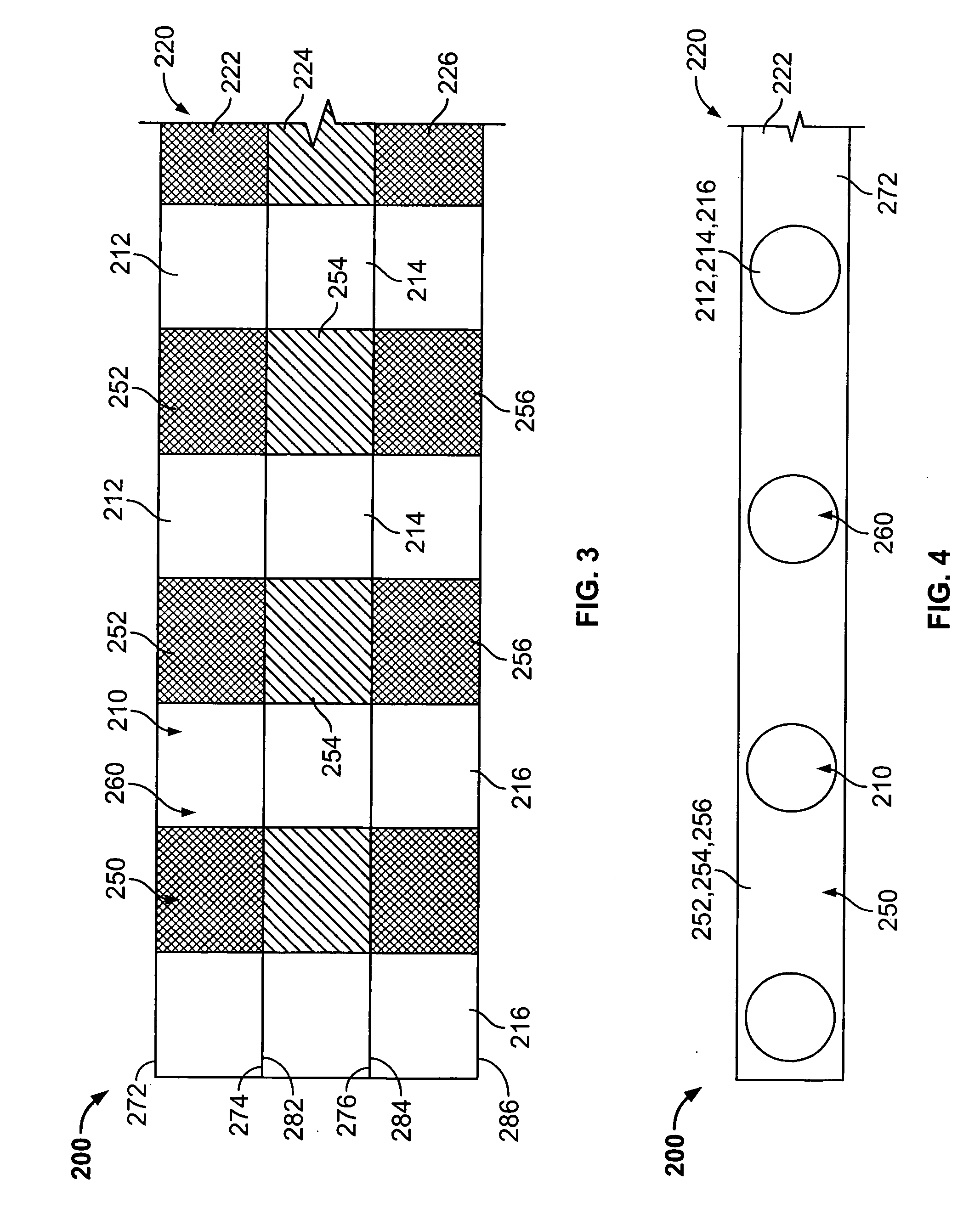
[0023] Another object of the present invention is to provide a rigid frame that includes microstructure, but to the extent the rigidity of the frame is not compromised. In reference to embodiments of filter microstructure integrated with a rigid frame, either manufactured with a one-shot or two-shot molding process, the frame itself may include filtration microstructure. Filtration microstructure positioned within the frame further enhances and facilitates flow of the matter being filtered.

Problems solved by technology

Although micro-filters can be made from woven materials, a problem is that the material can shift creating inconsistent pore sizes and an erratic mesh.
Extrusion does not allow for small pore sizes required by micro-filters.
Manufacturing of filter devices consisting of a rigid frame and an insert-molded mesh is complex when it comes to precisely placing the screen-type structure into the mold cavity.
Typically, it is difficult to create projections on a mold cavity surface that allow for injection molded fine openings.
Furthermore, the manufacturing techniques to create fine openings disclosed in Stamsted and Li are expensive and non-economical.

Method used


Image

  • System and method of micromolded filtration microstructure and devices
  • System and method of micromolded filtration microstructure and devices
  • System and method of micromolded filtration microstructure and devices

Examples


Embodiment Construction

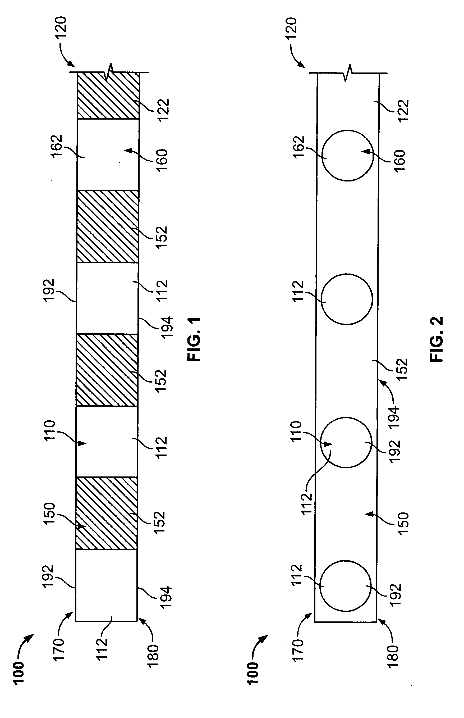
[0042]FIGS. 1 and 2 illustrate a single layer filtration microstructure assembly 100 that includes a microstructure layer 120. Layer 120 is created by a one-shot molding process and includes a support element 150 and a filter element 110 that create a tortuous channel 160. More specifically, FIGS. 1 and 2 illustrate a single layer of microstructure 122 that includes a plurality of support elements 152 and a plurality of filter elements 112. The filter elements 112 create tortuous channels 162 to filter matter. The channels 162 define an inlet surface 170 of openings192 and an outlet surface 180 of openings 194.

[0043] As shown in FIG. 2, channel 162 is cross-sectionally depicted as a straight-through hole configuration from the inlet surface 170 to outlet surface 180, although any configuration is contemplated, for example, a configuration with an inlet opening 192 of different size and / or shape compared to the outlet opening 194 of the channel 162, thus varying the cross-sectional ...


PUM

PropertyMeasurementUnit
Lengthaaaaaaaaaa
Lengthaaaaaaaaaa
Lengthaaaaaaaaaa

Abstract

Filtration microstructure comprises a micromolded layer including a support element and a filter element that creates a tortuous channel with an inlet surface of openings and an outlet surface of openings for filtering matter. Microstructure layers can be stacked upon one another creating a labyrinth network of tortuous channels. The openings of the filtration microstructure are micromolded between and including 30 micron and 1200 micron. The support element, or wall thickness, between channels is between and including 90 micron and 3600 micron. Thus, the wall thickness to channel opening ratio is between and including 1:1 and 10:1, with a preferred ratio at 3:1. The filtration microstructure enhances and facilitates flow or navigation of particles to pass. Additionally, micro-filter assemblies with an integrated frame and filtration microstructure can be micromolded. Micromolding filtration microstructure eliminates the processing and manufacturing of filtration devices and materials including woven and extruded material.

Description

RELATED APPLICATIONS [0001] This application claims the priority of U.S. Patent Application Ser. No. 60 / 742,673 filed on Dec. 6, 2005, incorporated herein by reference.FIELD OF THE INVENTION [0002] The present invention relates generally to filtration and more particularly, to a system and method of micromolded filtration microstructure. BACKGROUND OF THE INVENTION [0003] Various types of filters are used for sieving matter, including fluids. Filters commonly separate smaller particles of matter from larger particles of matter. Matter can be solid, semi-solid or liquid. Filters are widely used in liquid and solid separation, gas filtration and dust collection. Filters provide a plurality of pores, or holes, through which particles (liquid or solid) must navigate to pass. Those particles not sized small enough to pass through the pores are trapped and thus separated out. The pore size, shape and quantity each vary amongst filters. [0004] Filters come in many shapes and sizes dependin...

Claims


Application Information

Patent Timeline
IPC IPC(8): B01D24/00
CPCB01D29/012B01D46/10B29L2031/756B29L2031/14B29C2045/0094
Inventor KAY, RONALD J.
Owner KAY RONALD J
Learn More