Rotating Electrical Machine with a Transmission and a Driving Apparatus Using the Same

a technology of rotating electrical machines and driving apparatuses, which is applied in the direction of mechanical energy handling, magnetic circuit shape/form/construction, windings, etc., can solve the problems of not contributing the design of the motor cannot but have a margin, and the construction does not contribute to the miniaturization effect of the whole system. , to achieve the effect of easy contiguousness with organic materials

Inactive Publication Date: 2007-07-05
ENOMOTO YUJI +4
View PDF13 Cites 5 Cited by
  • Summary
  • Abstract
  • Description
  • Claims
  • Application Information

AI Technical Summary

Benefits of technology

[0010] Since the annular core containing the annular field coil and the organic material is used, lubricating oil for lubrication of the transmission d

Problems solved by technology

However, this construction does not contribute to miniaturization of a whole system even when a motor itself is made small in size, because a mechanical torque converter becomes large.
Therefore, there is caused a problem that an outside diameter of a motor becomes larger than a minimum outside diameter of a motor, which outputs a necessary torque, and so even when a large torque can be materialized by gear reduction, a whole system cannot be increased in effect of miniat

Method used


Image

  • Rotating Electrical Machine with a Transmission and a Driving Apparatus Using the Same
  • Rotating Electrical Machine with a Transmission and a Driving Apparatus Using the Same
  • Rotating Electrical Machine with a Transmission and a Driving Apparatus Using the Same

Examples


first embodiment

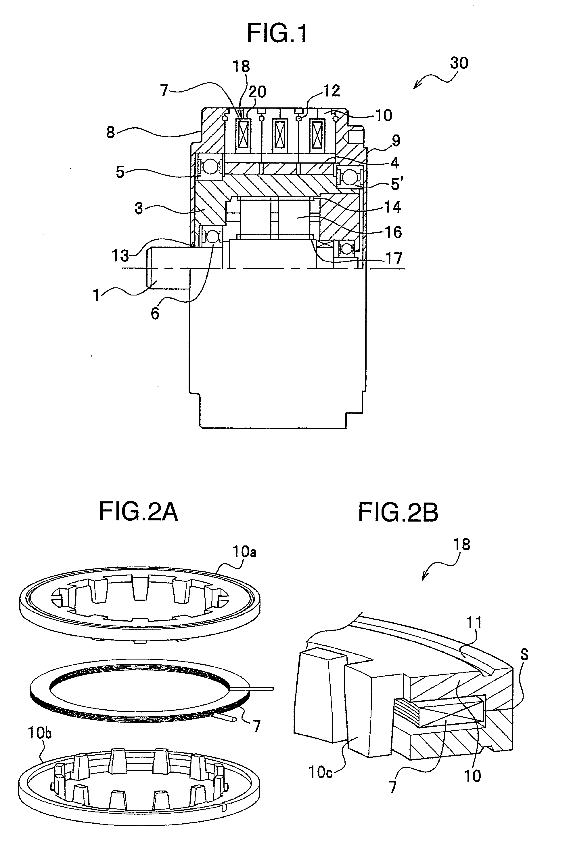
[0027] A rotating electrical machine with a transmission, according to an embodiment of the invention, will be described with reference to FIGS. 1 and 2. FIG. 1 is a longitudinal sectional view showing a reduction motor 30 comprising a rotating electrical machine with a transmission and FIGS. 2A and 2B are perspective views showing a claw teeth core 10 used for a stator of the reduction motor 30.

[0028] In FIG. 1, the reduction motor 30 according to the embodiment mainly comprises three stators composed of field coils 7 provided inside the annular-shaped claw teeth core 10, a rotating shaft 3 provided on a surface thereof with a cylindrical-shaped rotor 4, which is magnetized in multi-poles, and a transmission (described later) provided inside the rotating shaft 3 to reduce the rotating speed of an output shaft 1.

[0029] In FIGS. 2A and 2B, a stator 18 comprises two annular-shaped claw teeth cores 10a, 10b made of a soft magnetic material such as powder core, etc. and the field coil...

second embodiment

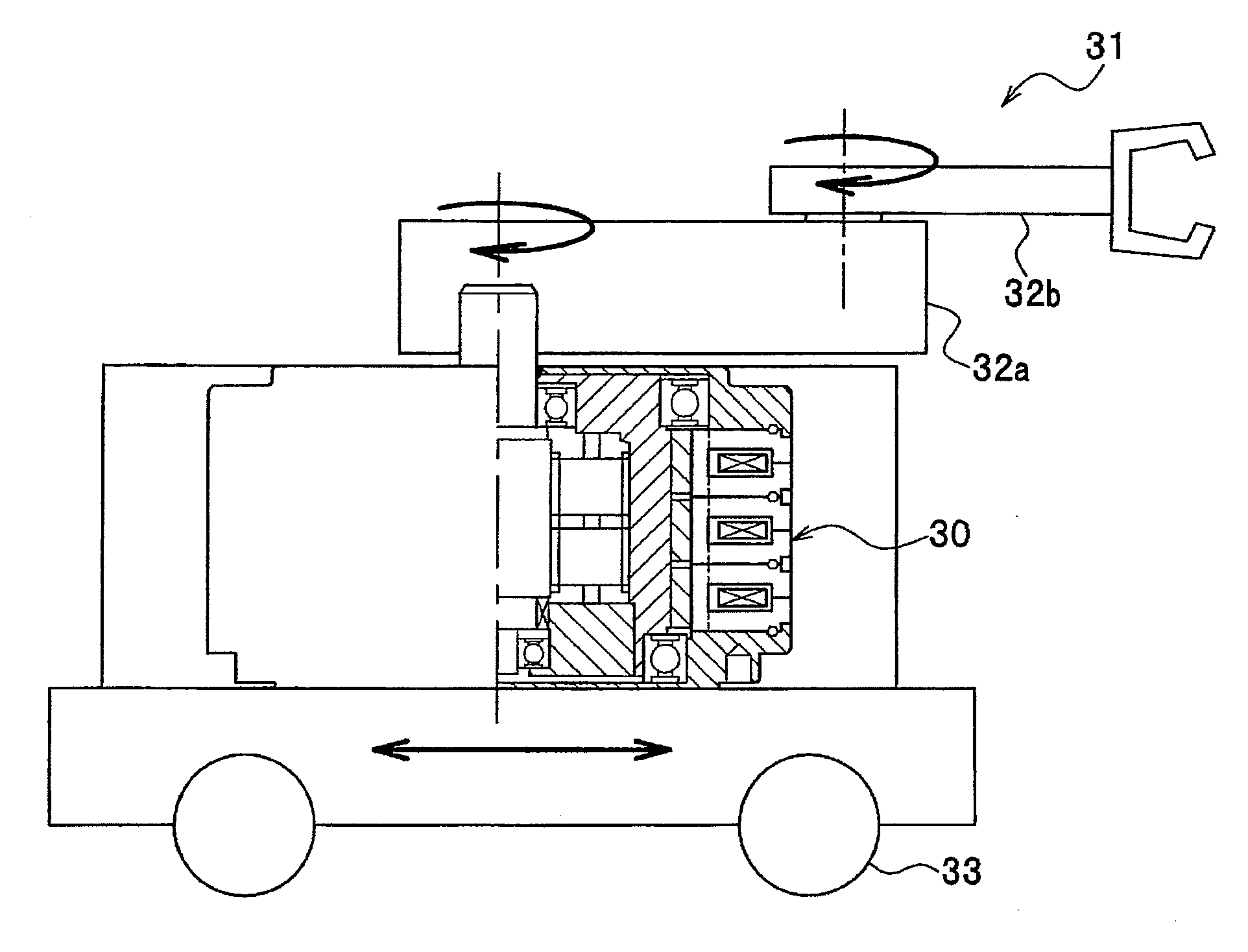
[0047] While the preceding embodiment has been described with respect to a motor being a rotating electrical machine, a driving apparatus using the motor can be constructed. Automotive equipment or a moving robot shown in FIG. 7 is conceivable as an example of the driving apparatus.

[0048] Use for articulate portions of an arm, which revolves and needs a large torque, of a moving body such as a moving robot (mobile robot) shown in FIG. 7 makes it possible to lighten the moving body to ensure a battery life for the moving body. A reduction motor 30 is mounted in a body of a moving robot 31, which can move in a longitudinal direction with the use of wheels 33, the reduction motor 30 revolving a swing arm 32a in a horizontal direction, and another motor received in the swing arm 32a revolves a swing arm 32b in the horizontal direction.

[0049] Also, since many motors are used in one automotive equipment, there is caused a problem that in a situation intended for an improvement in automo...


PUM


Abstract

A rotating electrical machine with a transmission, comprises a stator including a field coil arranged annularly, a cylindrical-shaped rotor, which rotates within the stator, transmissions provided within the cylindrical-shaped rotor, and housings to contain at least the rotor, the transmissions, and lubricating oil, and wherein the stator comprises the annular field coil and an annular core, in which the annular field coil and an organic material are contained and on an inner peripheral surface of which are provided a plurality of projecting claws.

Description

BACKGROUND OF THE INVENTION [0001] The present invention relates to a rotating electrical machine with a transmission, which comprises a core provided with a plurality of teeth, and a driving apparatus using the same. [0002] Motors are used as drive equipment to convert an electric energy into a mechanical output in industrial field, household electrical field, automotive field and the like. Motors as power equipment in these fields are generally demanded to be small in size and to be high in torque. [0003] As a way to increase an output torque, it is conceivable to amplify torque with a reduction mechanism (transmission). According to this, output can be increased by increasing the rotating speed of a motor while the motor remains same in gap magnetic flux density and opposed area. Generally, in uses with a large torque, such way finds an example used in a method of arranging a reduction mechanism (transmission) on an output shaft of a motor such as gear motors, etc. However, this ...

Claims


Application Information

Patent Timeline
IPC IPC(8): H02K37/14H02K7/06
CPCH02K1/145H02K3/44H02K5/10H02K21/145H02K7/06H02K7/116H02K5/128
Inventor ENOMOTO, YUJIITO, MOTOYAMASAKI, RYOSOOHIWA, SHOJIISHIHARA, CHIO
Owner ENOMOTO YUJI
Why Eureka
Try Eureka