Reluctance motor

Inactive Publication Date: 2007-07-05
OKUMA CORP
View PDF10 Cites 43 Cited by
  • Summary
  • Abstract
  • Description
  • Claims
  • Application Information

AI Technical Summary

Benefits of technology

[0017] By making the circumferential slit segments smaller in width than the radial slit segments, it becomes possible to increase a diameter of a through hole formed in the rotor for inserting a shaft of the motor in the through hole. Further, in the circumferential slit segments of the smaller slit width, occurrence of a leakage flux can be suppressed by the placement of the permanent magnets. Because leakage flux is likely to occur, i

Problems solved by technology

Therefore, the motor of the fourth instance has a great torque ripple, and is not applicable to use for a spindle of a machine tool or the like in which a high degree of rotation accuracy is required.
However, such increased width of the slits 2; in particular, an increase in width of those located near the center of the rotor, leads to a problematic situation that the diameter of the shaft 6 cannot be widened.
To secure proper performance of the motor, however, a rare-ear

Method used


Image

  • Reluctance motor
  • Reluctance motor
  • Reluctance motor

Examples


Embodiment Construction

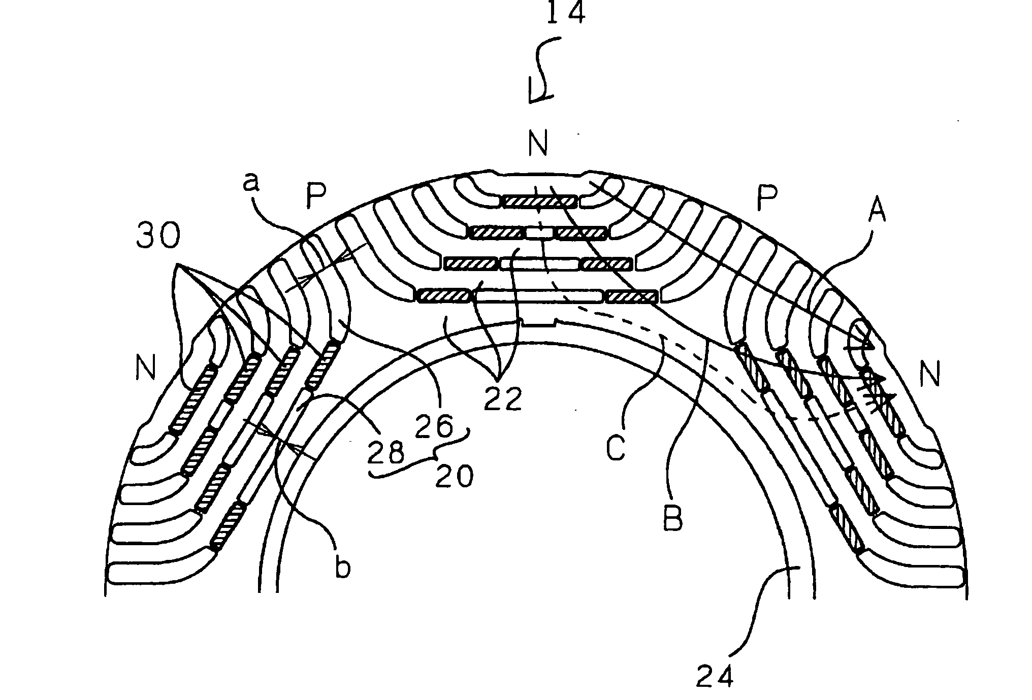
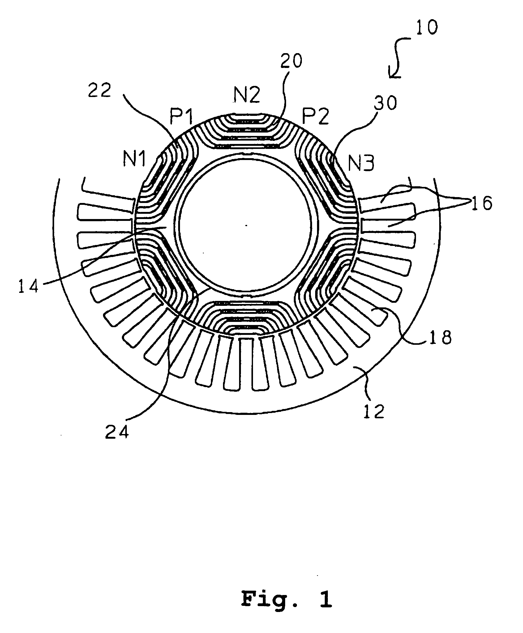
[0028] By reference to the drawings, a preferred embodiment of the present invention will be described below. FIG. 1 schematically shows a sectional structure of an electric motor according to the present embodiment. An electric motor 10 of this embodiment comprises a stator 12 which produces a rotating field and a rotor 14 rotated by an interaction with the rotating field. The stator 12 has teeth 16 arranged along an inner circumference thereof, and a coil conductor wire (winding) is inserted in slots 18 between the teeth 16 so as to wind the teeth 16. The rotating field is generated by applying a predetermined current to the winding. The rotor 14 is formed in a roughly cylindrical shape by laminating flat rolled magnetic steel sheets and strips having been die-cut into a predetermined shape. The flat rolled magnetic steel sheets and strips to be laminated have a sectional form as shown in FIG. 1. More specifically, a plurality of slits 20 extending side by side are die-cut to form...


PUM


Abstract

To form magnetic poles P on a rotor, a plurality of slits extending along a radial direction in a region close to the magnetic poles P and extending along a circumferential or chord direction in mid areas between the magnetic poles P are formed. The width b of circumferential slit segments extending along the circumferential or chord direction is narrower than the width a of radius slit segments extending along the radial direction. Permanent magnets are disposed in the narrowed segments of the slits to suppress leakage of magnetic flux. Thus, in a motor in which magnetic paths separated by the slits are formed on the rotor to provide regions having different magnetic reluctances in a circumferential direction of the rotor, a structure in which a through hole penetrated by an output shaft of the motor can have a large diameter is provided.

Description

[0001] The entire disclosure of Japanese Patent Application No. 2004-192543, including the specification, claims, drawings, and abstract, is incorporated herein by reference in its entirety. BACKGROUND OF THE INVENTION [0002] 1. Field of the Invention [0003] The present invention relates to an electric motor (hereinafter simply referred to as “a motor”) using magnetic torque in combination with reluctance torque, and in particular to a structure in relation to a magnetic path in a rotor of the motor. [0004] 2. Description of the Related Art [0005] As a first instance of background art of the present invention, there has been known a flux-barrier type reluctance motor such as that disclosed in Japanese Patent Laid-Open Publication No. Hei 11-206082. FIG. 5 shows an example of a cross sectional configuration of the motor. In this motor, a plurality of slits 2 are formed in a rotor 1 composed of laminated flat rolled magnetic steel sheets and strips, to thereby form a plurality of spli...

Claims


Application Information

Patent Timeline
IPC IPC(8): H02K21/12
CPCH02K29/03H02K1/246
Inventor YURA, MOTOZUMIYOKOCHI, TAKANORI
Owner OKUMA CORP
Why Eureka
Try Eureka