Eureka AIR delivers breakthrough ideas for toughest innovation challenges, trusted by R&D personnel around the world.

Broad-band fermi antenna design method, design program, and recording medium containing the design program

Inactive Publication Date: 2007-07-05
JAPAN SCI & TECH CORP
View PDF3 Cites 13 Cited by
  • Summary
  • Abstract
  • Description
  • Claims
  • Application Information

AI Technical Summary

Benefits of technology

[0023] According to the design method and design program of the broadband Fermi-antenna of the present invention, the radiation patterns of E-plane and H-plane can accord with the target value in the comparatively short time and the desired beam width can be given to both of E-plane and H-plane and also the side-lobes can be set to the low level, thereby being able to realize the Fermi-antenna suitable for the receiving element for millimeter-wave imaging.

Problems solved by technology

Although there is a method in which a mechanical scanning is used in the real-time imaging method, a complex mechanism for scanning is required in this method and also it takes a lot of time for measurement, therefore it is difficult to obtain the real-time image.
Generally, even if it strongly resonates for the E-plane and can receive the image from the object, there are many cases in which there is no directivity of the H-plane, so there are problems such as: the conversion efficiency decreases and a gain becomes low too.
Furthermore, it needs to amplify a received signal until the noise level of a detector, so it is required that the antenna has a high gain in the meaning of decreasing a loss to an amplifier.
Like this, there is such reality that is not easy to obtain the design guideline that realizes the radiation directivity required to the Fermi-antenna, and the design method of the TSA having a circular directivity was not presented even in the proposal described in the above-mentioned published document 1 and published document 2.

Method used


Image

  • Broad-band fermi antenna design method, design program, and recording medium containing the design program
  • Broad-band fermi antenna design method, design program, and recording medium containing the design program
  • Broad-band fermi antenna design method, design program, and recording medium containing the design program

Examples


Embodiment Construction

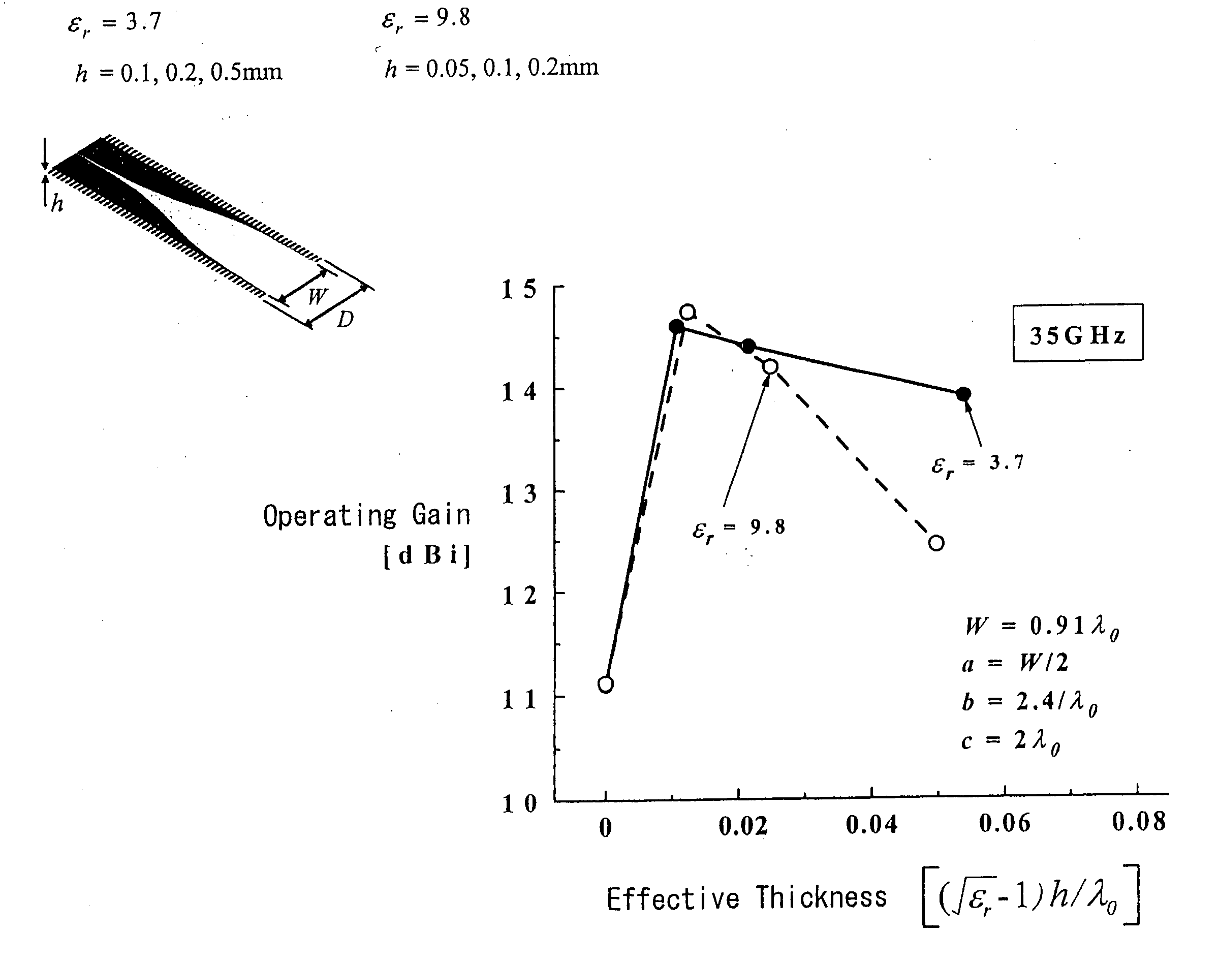
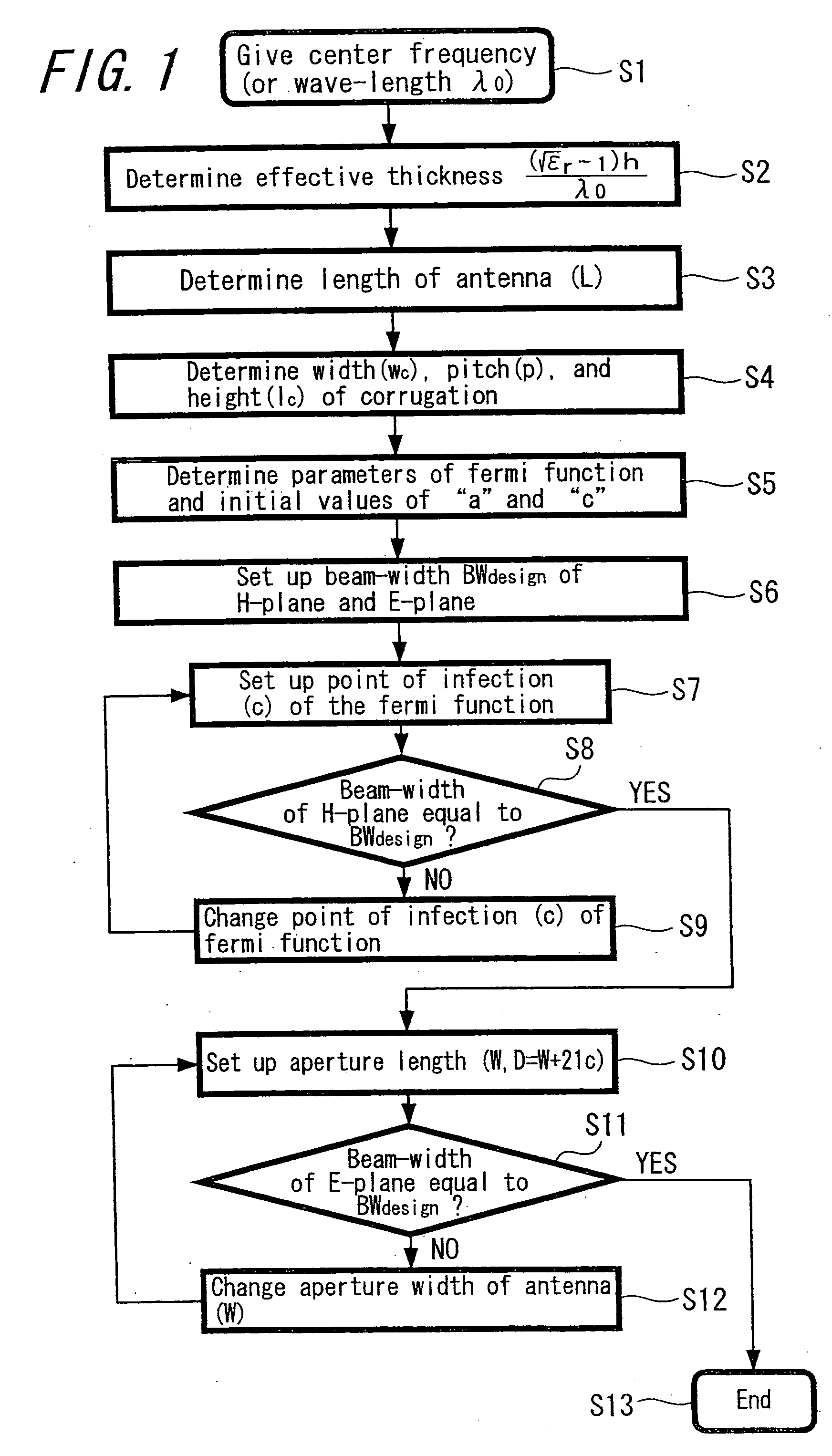
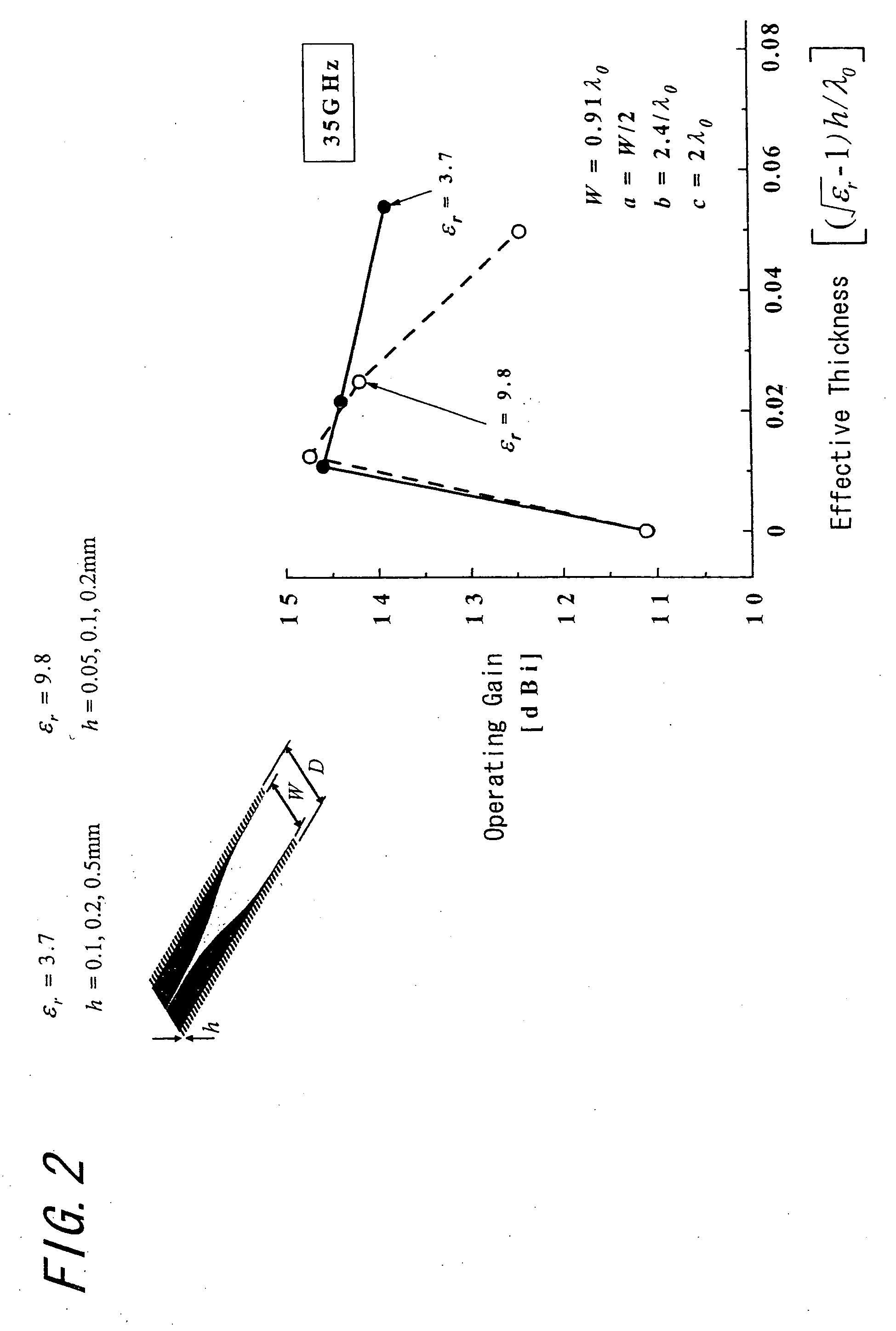
[0047] Hereinafter, embodiments of the design method of the Fermi-antenna that is a representative one of the broadband antenna according to the present invention are explained. As mentioned above, as the design parameters of Fermi-antenna, a relative dielectric constant ∈r of the dielectric substrate, the thickness of the substrate h, the length of antenna L, the width of corrugation structure Wc, the pitch p, the height of corrugation Lc and the Fermi-functional parameters (a, b and c) that determine the taper shape are actually many, and about how these values are chosen if the antenna that is small and that has the circular directivity of desired beam width BWdesign can be designed and also an example of the design to the 35 GHz frequencies are explained by using a design flow chart shown in FIG. 1.

[0048] The reasons that set the frequency to 35 GHz are: there is a frequency band in which an attenuation of radio-wave by the atmosphere is small in the vicinity of 35 GHz, so-call...


PUM


Abstract

There is provided a method for designing a corrugated Fermi antenna having a broad-band and circular directivity required for receiving an image by using a wave of millimeter order. As a first step, an inflection point of the Fermi-Dirac function as a taper function of the Fermi antenna is changed so as to set the beam width of plane H to a beam width having a target directivity. After the beam width of the plane H is set to the target value, the aperture width of the Fermi antenna is changed so as to set the beam width of the plane E to a beam width having a target directivity. Thus, by adjusting the beam width values of the planes H and E independently from each other and matching them with the target values, it is possible to design a Fermi-antenna having a broad-band and circular directivity in a short time.

Description

TECHNICAL FIELD [0001] The present invention relates to a design method of a wideband Fermi-antenna which is one of the TSAs (Tapered Slot Antennas), and to the design program and a recording medium for recording the design program. BACKGROUND ART [0002] A passive imaging in which an image is received in real time by using a millimeter-wave is able to obtain the image of all objects that include building and human body without being influenced by the weather, because of this the commercialization is being expected. The millimeter-wave indicates the electromagnetic wave in which the wave-length is approximately the range from 10 mm to 1 mm, and corresponds to 30 GHz to 300 GHz as the frequencies. In case of comparing it with ones of microwave band, the electromagnetic wave of millimeter-wave band has the characteristics such as: a) a small and light system can be realized; b) the interference and radio interference can be hardly caused because the narrow directivity is obtained; c) i...

Claims


Application Information

Patent Timeline
IPC IPC(8): H01Q13/10H01Q1/18H01Q1/38H01Q13/08
CPCH01Q1/18H01Q13/085H01Q13/08H01Q1/38H01Q21/22
Inventor MIZUNO, KOJISAWAYA, KUNIOSATO, HIROYASUWAGATSUMA, YOSHIHIKO
Owner JAPAN SCI & TECH CORP
Why Eureka
Eureka Blog
Learn More