
Continuously variable transmission

a transmission ratio and continuous technology, applied in the field of transmissions, can solve the problem of unfulfilled need for cvt, and achieve the effect of facilitating the axial translation of the traction sun and the adjustment of the transmission ratio

Inactive Publication Date: 2007-07-05
FALLBROOK INTPROP COMPANY
View PDF99 Cites 174 Cited by
  • Summary
  • Abstract
  • Description
  • Claims
  • Application Information

AI Technical Summary

Benefits of technology

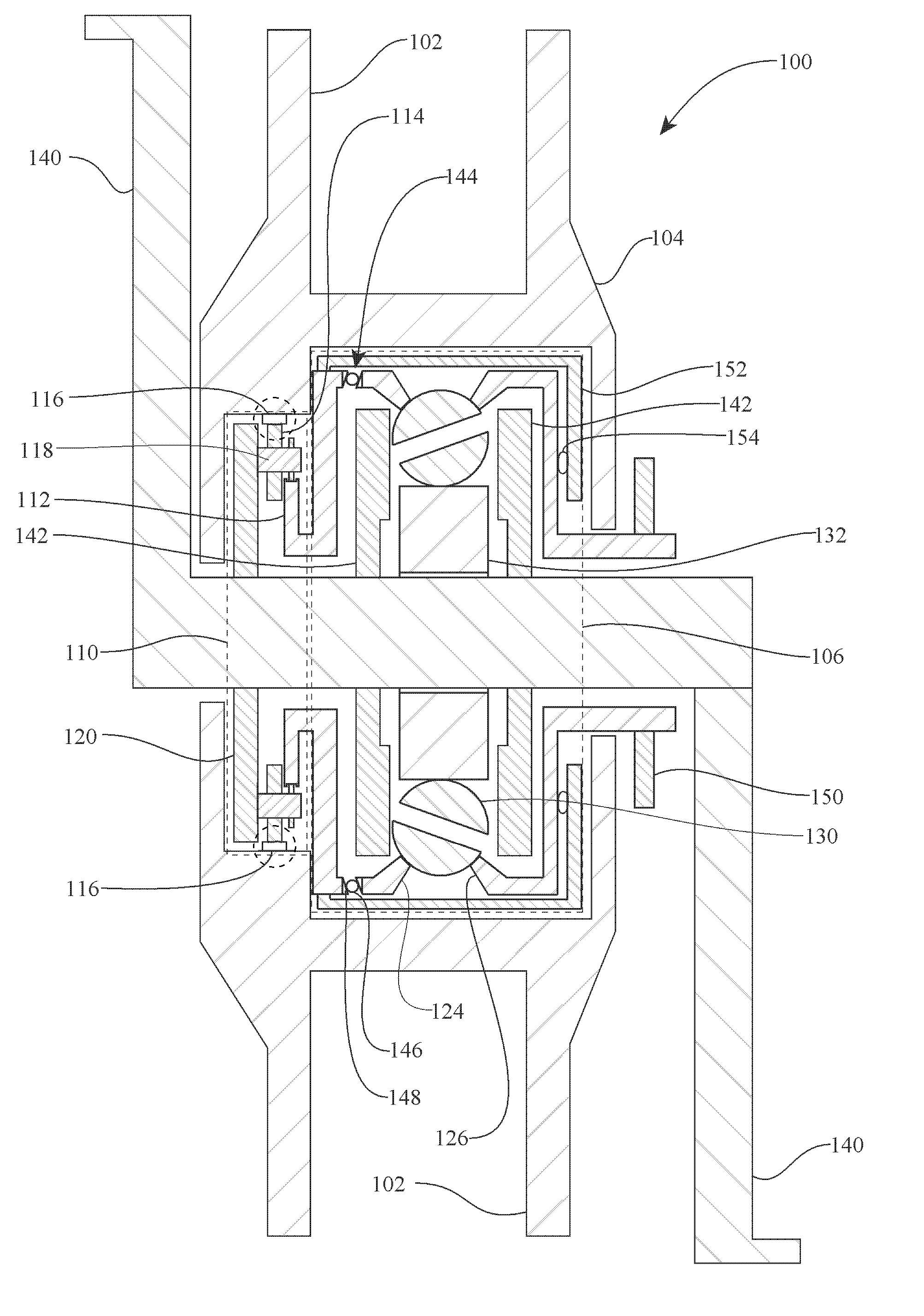
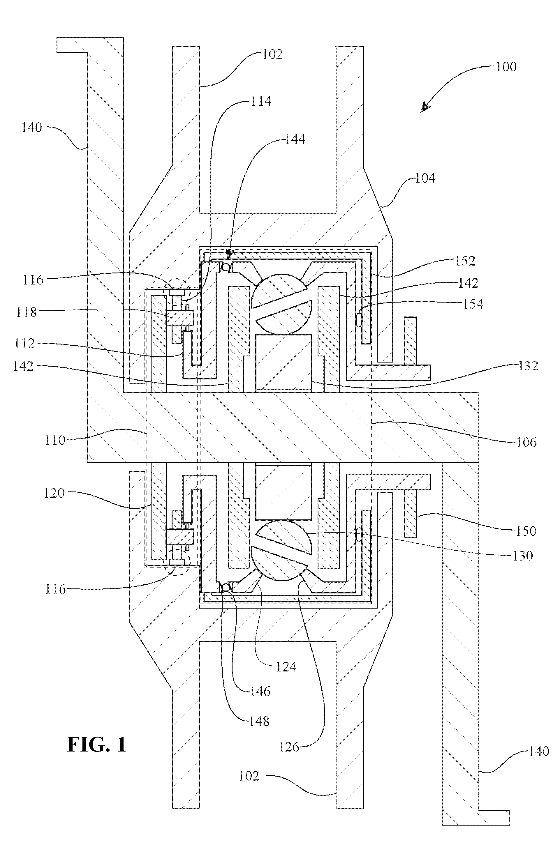
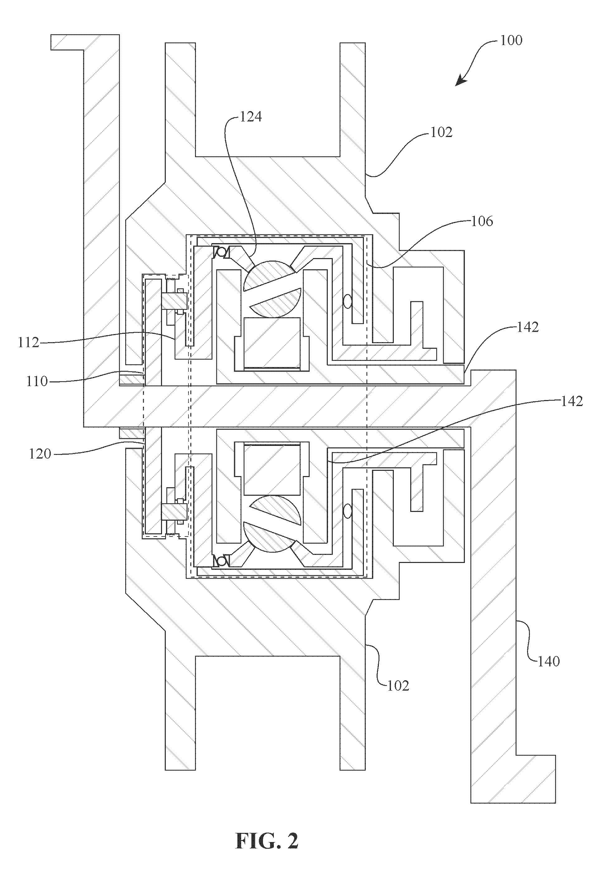
[0011] Still another aspect of the invention is directed to a shift screw and a shift pin hub for facilitating the adjustment of a transmission ratio. In another regard, the invention relates to a device for actuating an axial translation of an idler or traction sun as the transmission ratio is adjusted. In one embodiment, the traction sun actuation device includes a plurality of cam rollers configured to interface with a cam surface of a pivot arm. Another aspect of the invention covers the pivot arms having an integral cam surface for facilitating the axial translation of the traction sun.

Problems solved by technology

However, there remains an unfulfilled need for a CVT that is received and supported by the frame members of the bicycle at a location forward of the rear wheel or rear wheel hub.

Method used


Image

  • Continuously variable transmission
  • Continuously variable transmission
  • Continuously variable transmission

Examples


Embodiment Construction

,” one will understand how the features of the systems and methods provide several advantages over related traditional systems and methods.

[0008] One aspect of the invention relates to a bicycle having a plurality of bicycle frame members, a crankshaft operationally coupled to one or more cranks of the bicycle, and a continuously variable transmission (CVT) coaxially coupled with, and coaxially mounted about, the crankshaft.

[0009] Another aspect of the invention is addressed to a bicycle having a crankshaft coupled to a rotatable planetary gear set carrier coupled, and a plurality of planet gears coupled to said carrier. A ring gear, rotationally constrained, can be coupled to the planet gears, which can be coupled to a sun gear coupled. A first traction ring is operationally coupled to the sun gear, and a plurality of traction planets are coupled to the traction ring. A second traction ring is coupled to the traction planets. Power is transferred sequentially from the crankshaft t...


PUM


Abstract

Traction planets and traction rings can be operationally coupled to a planetary gearset to provide a continuously variable transmission (CVT). The CVT can be used in a bicycle. In one embodiment, the CVT is mounted on the frame of the bicycle at a location forward of the rear wheel hub of the bicycle. In one embodiment, the CVT is mounted on and supported by members of the bicycle frame such that the CVT is coaxial with the crankshaft of the bicycle. The crankshaft is configured to drive elements of the planetary gearset, which are configured to operationally drive the traction rings and the traction planets. Inventive component and subassemblies for such a CVT are disclosed. A shifting mechanism includes a plurality of pivot arms arranged to pivot about the centers of the traction planets as a shift pin hub moves axially.

Description

RELATED APPLICATIONS [0001] This application claims priority to U.S. provisional patent application No. 60 / 738,865, which was filed on Nov. 22, 2005 and is hereby incorporated herein by reference in its entirety.BACKGROUND OF THE INVENTION [0002] 1. Field of the Invention [0003] The field of the invention relates generally to transmissions, and more particularly to continuously variable transmissions (CVTs). [0004] 2. Description of the Related Art [0005] Embodiments of the CVTs disclosed here can be used in any machine, device, vehicle, etc., where it is desired to adjust the ratio of input speed to output speed. A bicycle is one such application. The drivetrain of a bicycle typically consists of pedals coupled to cranks for driving a crankshaft, which is received in, and supported by, frame members of the bicycle. The crankshaft is coupled to a sprocket that transfers power to the rear wheel of the bicycle by a chain. A cog at the rear wheel receives power from the chain and is ad...

Claims


Application Information

Patent Timeline
Patent Type & Authority Applications(United States)
IPC IPC(8): F16H47/08B62M1/36
CPCB62M9/08B62M11/145F16H15/28Y10T74/19851B62M1/36F16H15/503Y10T74/20177F16H15/52B62M11/04B62M11/00F16H47/08
Inventor MILLER, DONALDCSMITHSON, ROBERT A.POHL, BRAD P.LOHR, CHARLES B.NICHOLS, JON M.
Owner FALLBROOK INTPROP COMPANY
Learn More