Differential planetary gear apparatus and starting apparatus and method for differential planetary gear apparatus
a gear apparatus and planetary gear technology, applied in the direction of gearing, mechanical equipment, differential gearings, etc., can solve the problems of unsuitable high-speed rotation type of differential planetary gear apparatus, large radial size of radial device, complicated structure thereof, etc., to achieve accurate and smooth speed change, high mechanical efficiency, and high efficiency
- Summary
- Abstract
- Description
- Claims
- Application Information
AI Technical Summary
Benefits of technology
Problems solved by technology
Method used
Image
Examples
first embodiment
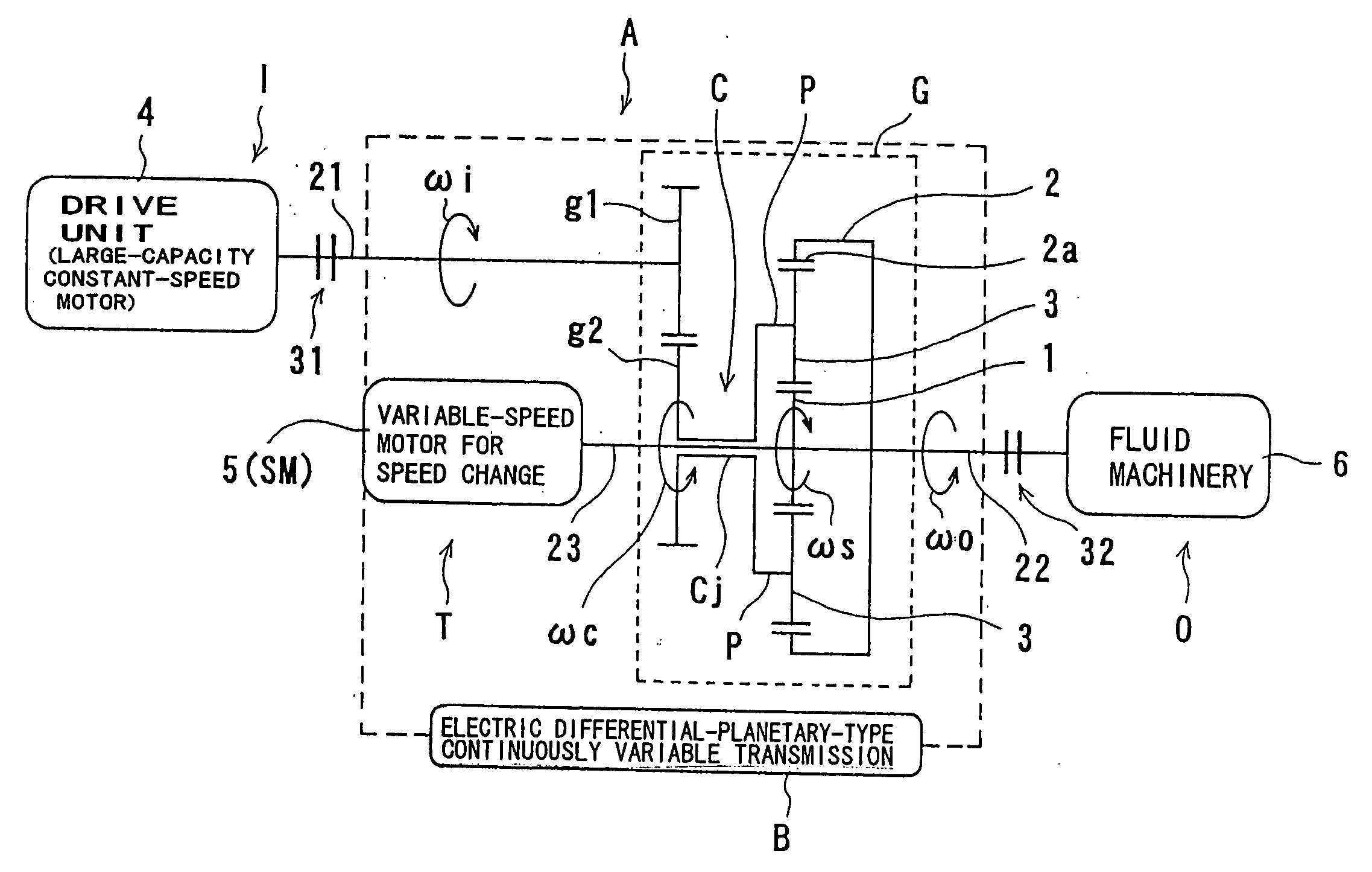
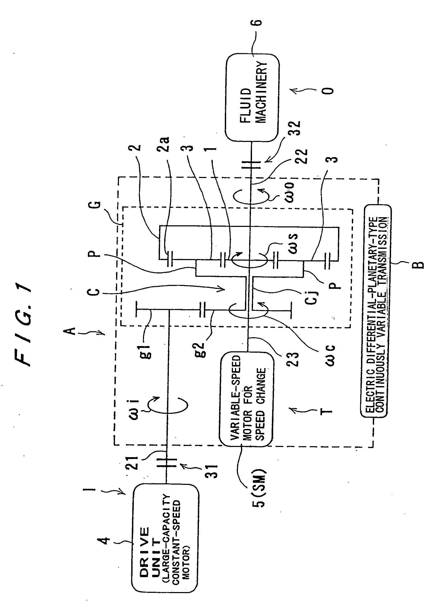
[0055] First, a differential planetary gear apparatus will be described with reference to FIG. 1.
[0056] In FIG. 1, the differential planetary gear apparatus, which is indicated by a reference sign A as a whole, comprises an electric differential-planetary-type continuously variable transmission B having an input shaft 21 and an output shaft 22, a drive unit 4 comprising a large-capacity constant-speed motor disposed at an input side I, i.e., connected to one end of the input shaft 21 via an input-side clutch 31, and a fluid machinery 6, such as a turbo machinery, disposed at an output side O, i.e., connected to one end of the output shaft 22 via an output-side clutch 32.
[0057] The electric differential-planetary-type continuously variable transmission B comprises a differential planetary gear assembly G having an input shaft and an output shaft (i.e., the input shaft 21 and the output shaft 22) and a speed-change drive shaft 23, and a small-capacity variable-speed motor 5 for spee...
second embodiment
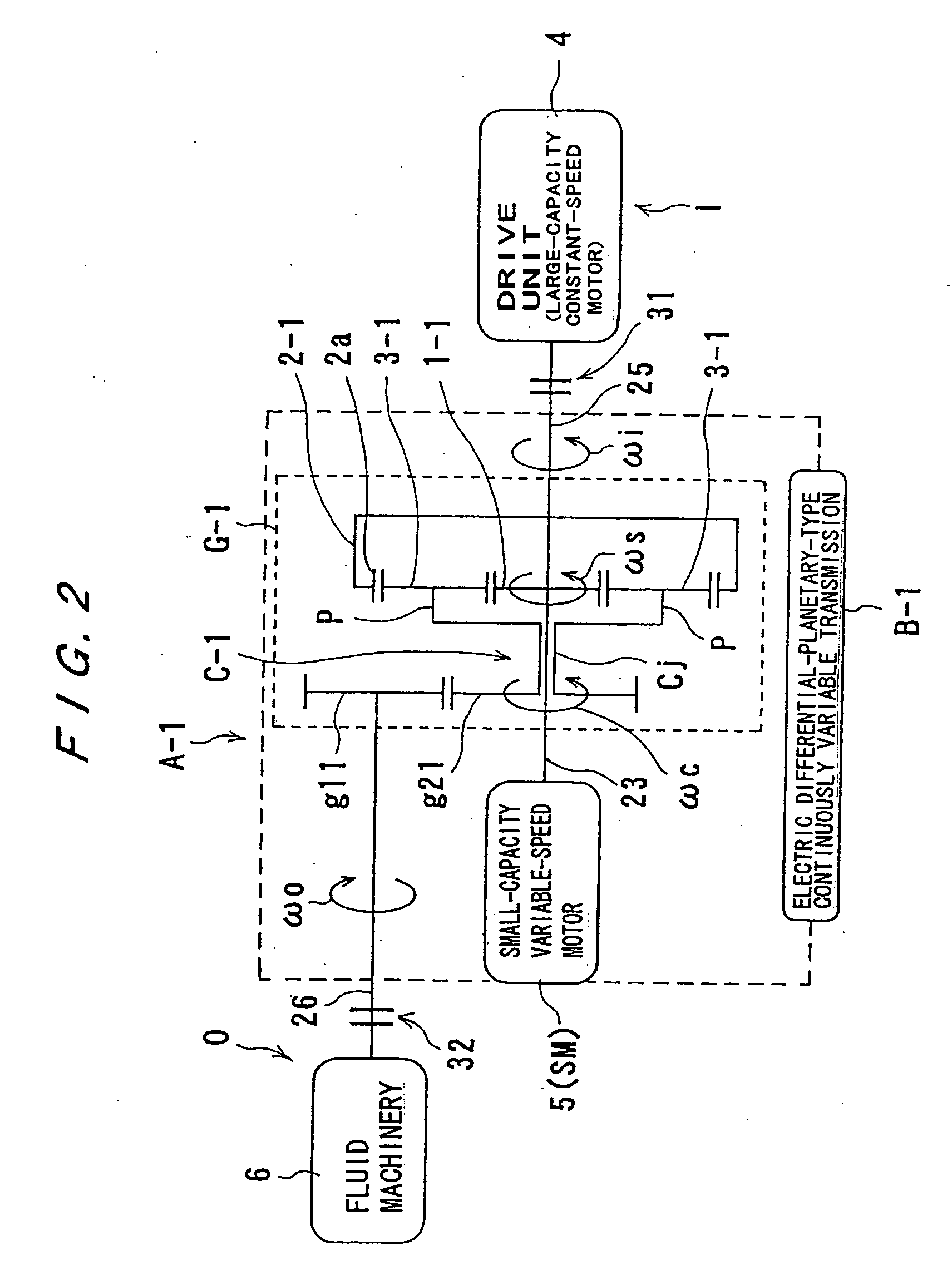
[0073] Next, a second embodiment will be described with reference to FIG. 2.
[0074] In FIG. 2, a differential planetary gear apparatus, which is indicated by a reference sign A-1 as a whole, comprises an electric differential-planetary-type-type continuously variable transmission B-1 having an input shaft 25 (disposed at the right side in the drawing) and an output shaft 26 (disposed at the left side in the drawing), a drive unit 4 comprising a large-capacity constant-speed motor disposed at an input side I, i.e., connected to one end of the input shaft 25 via an input-side clutch 31, and a fluid machinery 6 disposed at an output side O, i.e., connected to one end of the output shaft 26 via an output-side clutch 32.
[0075] The electric differential-planetary-type-type continuously variable transmission B-1 comprises a differential planetary gear assembly G-1 having an input shaft and an output shaft (i.e., the input shaft 25 and the output shaft 26) and a speed-change drive shaft 23,...
third embodiment
[0083] Next, a third embodiment will be described with reference to FIG. 3.
[0084] In FIG. 3, a differential planetary gear apparatus, which is indicated by a reference sign A-2 as a whole, has a structure in which a speed-change gear 7, such as a speed-increasing gear or a speed-decreasing gear, is added to the first embodiment shown in FIG. 1. This speed-change gear 7 is disposed on the output shaft 22 at a location between the ring gear 2 and the output-side clutch 32.
[0085] According to the third embodiment shown in FIG. 3, the speed change can be performed in a wider speed range, compared with the first embodiment shown in FIG. 1.
PUM
 Abstract
Description
Claims
Application Information
 - R&D
- Intellectual Property
- Life Sciences
- Materials
- Tech Scout
- Unparalleled Data Quality
- Higher Quality Content
- 60% Fewer Hallucinations
Browse by: Latest US Patents, China's latest patents, Technical Efficacy Thesaurus, Application Domain, Technology Topic, Popular Technical Reports.
© 2025 PatSnap. All rights reserved.Legal|Privacy policy|Modern Slavery Act Transparency Statement|Sitemap|About US| Contact US: help@patsnap.com


