Radioactive-emission-measurement optimization to specific body structures

a radioactive emission measurement and optimization technology, applied in the field of nuclear imaging, can solve the problem that the two-dimensional image does not lend itself to the generation of images, and achieve the effect of rapid, inexpensive preliminary indication, and inexpensive and convenient hardwar

Inactive Publication Date: 2007-07-05
SPECTRUM DYNAMICS MEDICAL LTD
View PDF99 Cites 73 Cited by
  • Summary
  • Abstract
  • Description
  • Claims
  • Application Information

AI Technical Summary

Benefits of technology

[0061] Additionally, U.S. Pat. No. 6,671,541, to Bishop et al. relates to a cardiovascular imaging and functional analysis system and method, wherein a dedicated fast, sensitive, compact and economical imaging gamma camera system that is especially suited for heart imaging and functional analysis is employed. The cardiovascular imaging and functional analysis system of the present invention can be used as a dedicated nuclear cardiology small field of view imaging camera. The disclosed cardiovascular imaging system and method has the advantages of being able to image physiology, while offering an inexpensive and portable hardware, unlike MRI, CT, and echocardiography systems. The cardiovascular imaging system of the invention employs a basic modular design suitable for cardiac imaging with one of several radionuclide tracers. The detector can be positioned in close proximity to the chest and heart from several different projections, making it possible rapidly to accumulate data for first-pass analysis, positron imaging, quantitative stress perfusion, and multi-gated equilibrium pooled blood (MUGA) tests. In a preferred embodiment, the Cardiovascular Non-Invasive Screening Probe system can perform a novel diagnostic screening test for potential victims of coronary artery disease. The system provides a rapid, inexpensive preliminary indication of coronary occlusive disease by measuring the activity of emitted particles from an injected bolus of radioactive

Problems solved by technology

In other words, while a wide-aperture, single-pixel detecting unit, such as that of FIG. 1A provides high efficiency, it does not lend itself t

Method used


Image

  • Radioactive-emission-measurement optimization to specific body structures
  • Radioactive-emission-measurement optimization to specific body structures
  • Radioactive-emission-measurement optimization to specific body structures

Examples


example 1

[0287] Referring further to the drawings, FIGS. 17A-17H schematically illustrate detecting units 12 and blocks 90 that may be considered for possible probe designs.

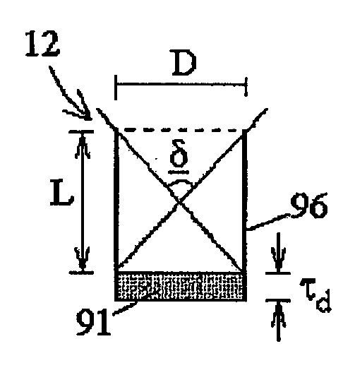
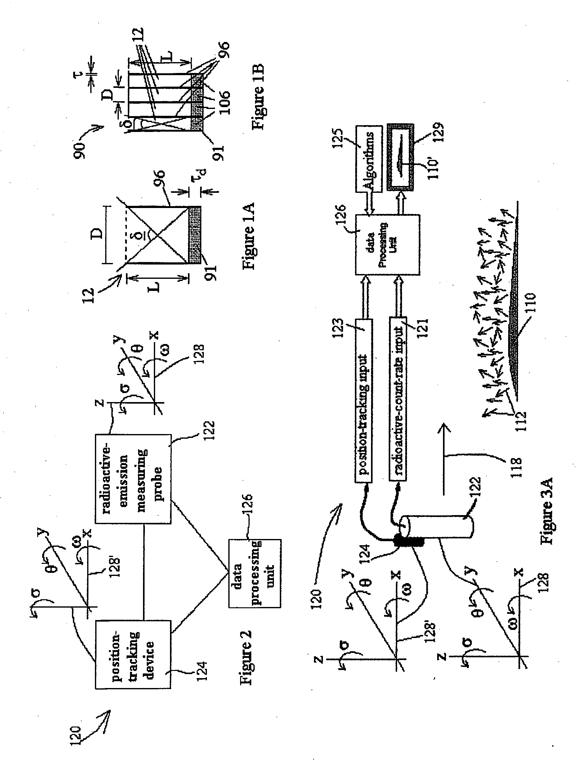
[0288]FIGS. 17A and 17B schematically illustrate side and top views, respectively, of the basic detecting unit 12 (see also FIG. 1A), having a detector 91 and a wide-bore collimator 96, formed as a tube, of a collection angle δ1.

[0289]FIGS. 17C and 17D schematically illustrate side and top views, respectively, of the detecting unit 12, with the collimator 96 formed as a wide angle collimator, of a collection angle δ2.

[0290]FIGS. 17E and 17F schematically illustrate side and top views, respectively, of the block 90 (see also FIG. 1B) of the detecting units 12, with the collimator 96 formed as a grid, and each of the detecting unit 12 having a collection angle δ3. As few as two or four, and as many as a hundred or several hundred of the detecting units 12 may be included in the block 90.

[0291]FIGS. 17G and 17H schematic...

example 2

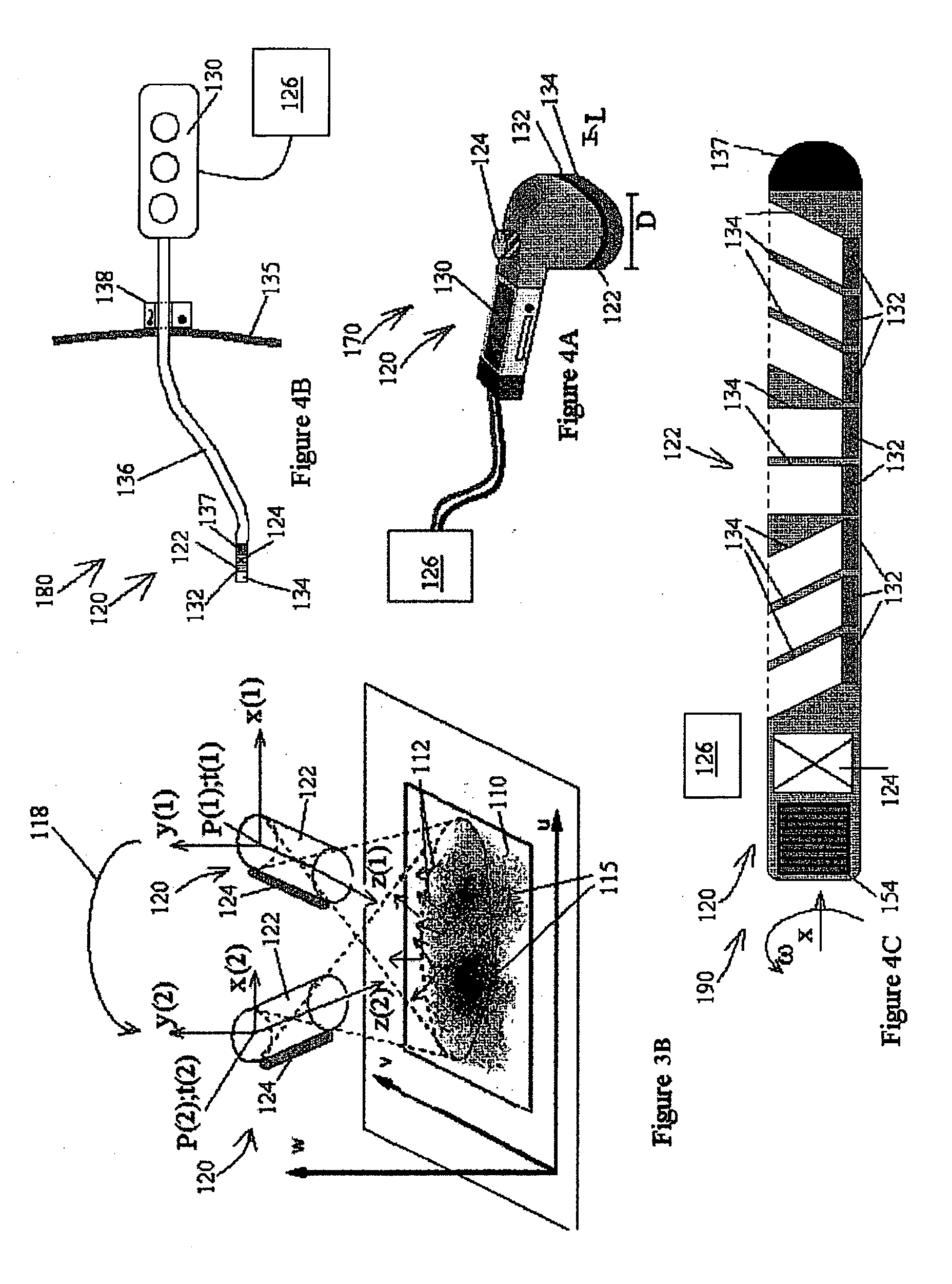
[0297] Referring further to the drawings, FIGS. 18A and 18B schematically illustrate the radioactive-emission-measuring probe 10, of the single detecting unit 12 (see FIGS. 1A and 17A). The single detecting unit 12 has a motion with respect to the housing 20, which is a combination of a rotational motion around the x-axis, in the direction of ω, denoted by an arrow 44, and a translational motion along the x-axis, denoted by an arrow 46.

[0298] As a consequence, a spiral trace 48 is formed, for example, on an inner surface of a body lumen 232, as seen in FIG. 18B.

[0299] Preferably, the motions of the detecting unit 12 are contained within the housing 20, so that the external surface of the probe 10 remains stationary. The external surface of the probe may be formed of a carbon fiber, a plastic, or another material, which is substantially transparent to nuclear radiation.

example 3

[0300] Referring further to the drawings, FIGS. 18C and 18D schematically illustrate the radioactive-emission-measuring probe 10, of the single block 90 (FIGS. 1B and 17E). Note that all the detecting units 12 of the single block 90 move as a single body. The single block 90 has a motion with respect to the housing 20, which is a combination of the rotational motion around the x-axis, in the direction of ω, denoted by the arrow 44, and the translational motion along the x-axis, denoted by the arrow 46.

[0301] As a consequence, a plurality of spiral traces 49 is formed, for example, on an inner surface of a body lumen, as seen in FIG. 18D.

[0302] Preferably, the motions of the block 90 are contained within the housing 20, so that the external surface of the probe 10 remains stationary, wherein the external surface of the probe is substantially transparent to nuclear radiation.


PUM

PropertyMeasurementUnit
Volumeaaaaaaaaaa
Density distribution functionaaaaaaaaaa
Radioactivityaaaaaaaaaa

Abstract

Systems, methods, and probes are provided for functional imaging by radioactive-emission-measurements, specific to body structures, such as the prostate, the esophagus, the cervix, the uterus, the ovaries, the heart, the breast, the brain, and the whole body, and other body structures. The nuclear imaging may be performed alone, or together with structural imaging, for example, by x-rays, ultrasound, or MRI. Preferably, the radioactive-emission-measuring probes include detectors, which are adapted for individual motions with respect to the probe housings, to generate views from different orientations and to change their view orientations. These motions are optimized with respect to functional information gained about the body structure, by identifying preferred sets of views for measurements, based on models of the body structures and information theoretic measures. A second iteration, for identifying preferred sets of views for measurements of a portion of a body structure, based on models of a location of a pathology that has been identified, makes it possible, in effect, to zoom in on a suspected pathology. The systems are preprogrammed to provide these motions automatically.

Description

RELATED APPLICATIONS [0001] This application is a continuation-in-part of PCT Patent Application No. PCT / IL2005 / 000575 filed on Jun. 1, 2005, which claims the benefit of U.S. Provisional Patent Application Nos. 60 / 648,690 filed on Feb. 2, 2005, 60 / 648,385 filed on Feb. 1, 2005, 60 / 640,215 filed on Jan. 3, 2005, 60 / 636,088 filed on Dec. 16, 2004, 60 / 635,630 filed on Dec. 14, 2004, 60 / 632,515 filed on Dec. 3, 2004, 60 / 632,236 filed on Dec. 2, 2004, 60 / 630,561 filed on Nov. 26, 2004, 60 / 625,971 filed on Nov. 9, 2004 and 60 / 575,369 filed on Jun. 1, 2004. [0002] This application is also a continuation-in-part of U.S. patent application Ser. No. 09 / 641,973 filed on Aug. 21, 2000. [0003] This application is also a continuation-in-part of U.S. patent application Ser. No. 10 / 343,792 filed on Feb. 4, 2003. [0004] This application is also a continuation-in-part of U.S. patent application Ser. No. 10 / 616,307 filed on Jul. 10, 2003. [0005] This application is also a continuation-in-part of U.S. ...

Claims


Application Information

Patent Timeline
IPC IPC(8): A61B6/00C08F210/00F02B1/00G01T1/164
CPCA61B6/00A61B6/4258G01T1/1644G06T7/0012A61B6/4266A61B6/481A61B6/54A61B6/02A61B6/06G01T1/1642G06T2207/10072
Inventor NAGLER, MICHAELDICHTERMAN, ELIZILBERSTEIN, YOELRAVHON, RANZIV, OMERROUSSO, BENNYBEN-HAIM, SHLOMO
Owner SPECTRUM DYNAMICS MEDICAL LTD
Why Eureka
Try Eureka