Shoulder joint prosthetic system

a shoulder joint and prosthetic technology, applied in the field of shoulder joint prosthetic systems, can solve the problems of deterioration of the bearing surface of the bone such as the glenoid, difficulty in repairing the joint, and particularly awkward shoulder joints to be satisfactorily addressed with mass produced prosthetic components

Inactive Publication Date: 2007-07-05
STANMORE IMPLANTS WORLDWIDE
View PDF7 Cites 153 Cited by
  • Summary
  • Abstract
  • Description
  • Claims
  • Application Information

AI Technical Summary

Benefits of technology

[0006] According to a first aspect of the present invention there is provided a glenoid prosthesis assembly for use in shoulder joint arthroplasty comprising a first, suitably shell/cup-shaped, component to be affixed to a scapula by fixing means, the fixing means suitably comprising bolts, screws or the like, and a smaller second, suitably shell/cup-shaped, component adapted to nest within the first component and having an articulation surface f

Problems solved by technology

Of the joints of the human body that may be repaired with prosthetic components, the shoulder joint is particularly awkward to satisfactorily address with mass produced prosthetic components.
The extent of damage to the processes of the scapula and especially to the glenoid cavity may vary greatly and when extreme can make repair of the joint extremely difficult.
Futhermore, the condition of bearing surfaces of the bone such as the glenoid may well deteriorate over time following installation of a prosthesis, through wear and te

Method used


Image

  • Shoulder joint prosthetic system
  • Shoulder joint prosthetic system
  • Shoulder joint prosthetic system

Examples


Embodiment Construction

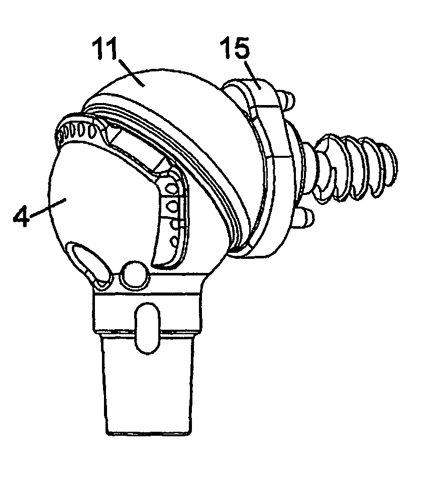
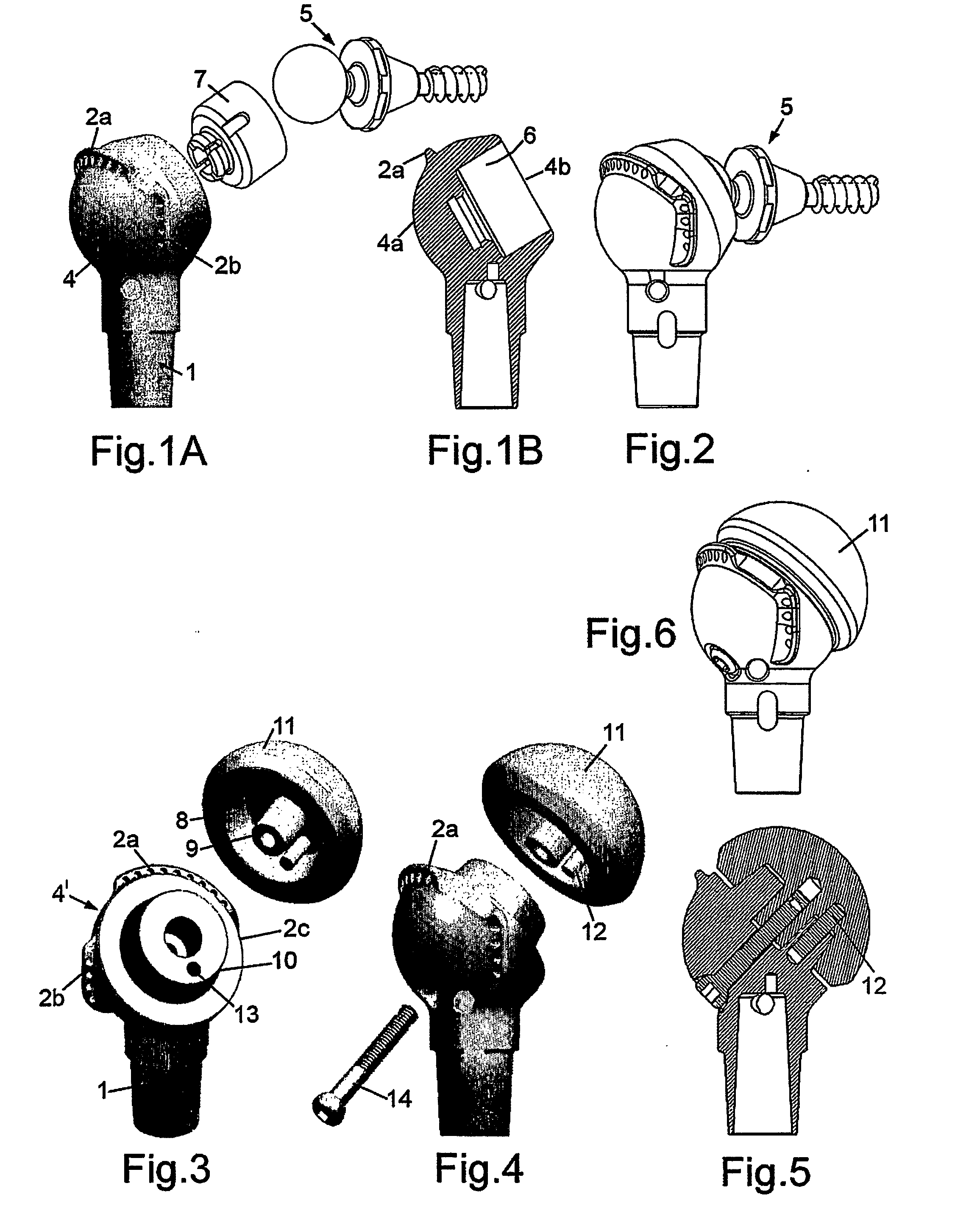
[0026] The device illustrated in FIGS. 1 to 6 is a prosthesis for the proximal humerus or rather is an upper part and head component of a modular prosthesis for the proximal humerus and which has a tubular shank 1 to receive an elongate stem component (not shown), if needed, that extends into the core of a resected humerus. Reference is made here to the Applicant's own earlier UK Patent Application No. GB 2370041 the content of which is incorporated herein by reference and that discloses the modular construction of a long bone prosthesis having a head portion with a separable stem component.

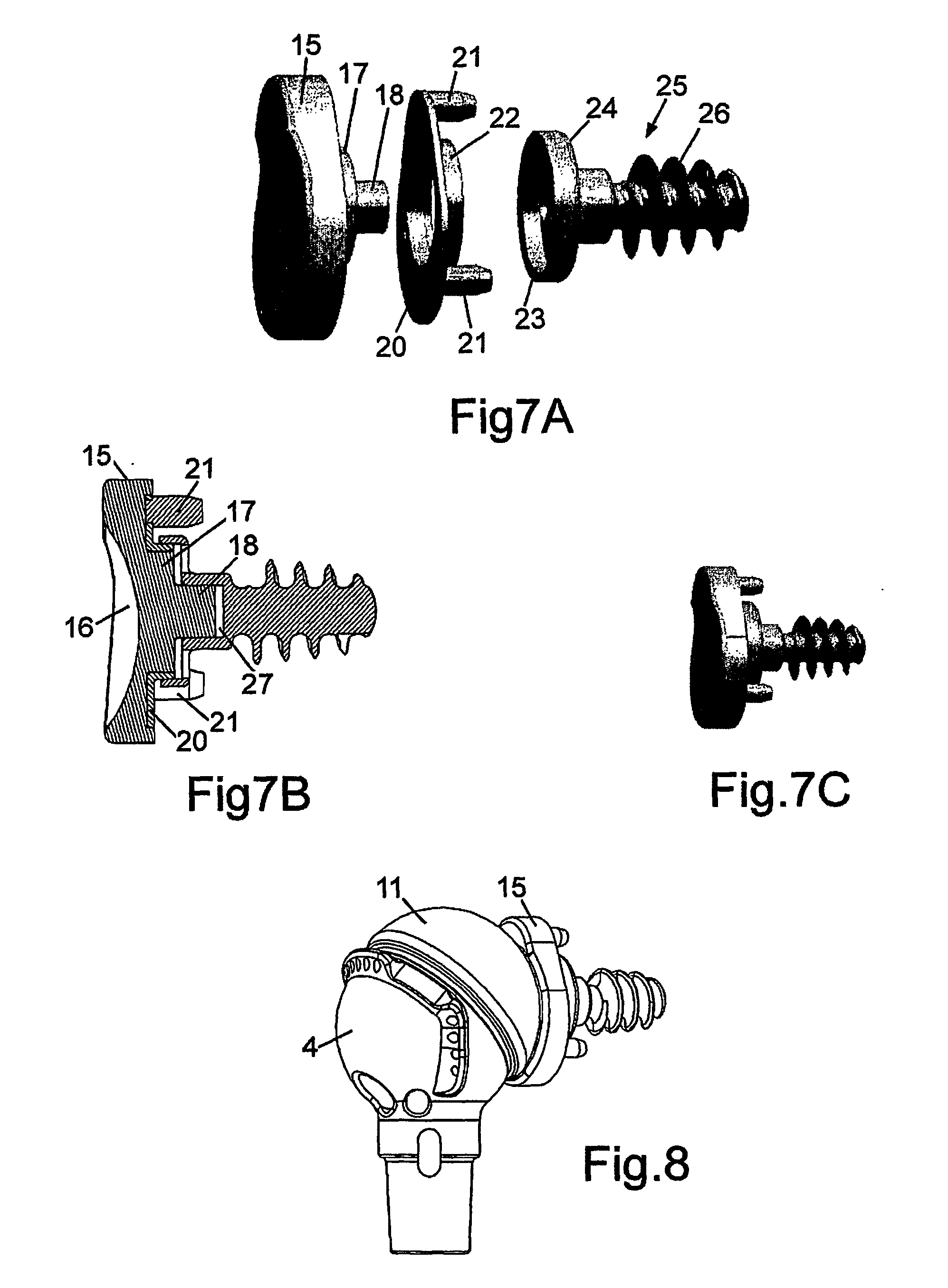
[0027] In the proximal humeral prosthesis illustrated in FIGS. 1A, 1B and 2 this is adapted to provide a reverse anatomy type shoulder joint. As shown in FIGS. 1A and 2, it is suited for use in combination with a Bayley-Walker™ glenoid screw prosthesis 5 or similar, such as is discussed later with reference to FIG. 9A, where the ball of the ball-and-socket shoulder joint is provided on the gleno...


PUM

PropertyMeasurementUnit
Lengthaaaaaaaaaa

Abstract

In a first aspect the present invention provides a glenoid prosthesis assembly for use in shoulder joint arthroplasty to address conditions where deterioration of the rotator cuff mechanism of the shoulder joint is severe, the assembly comprising a first shell component to be affixed to a scapula by fixing means, and a smaller second component adapted to nest within the first component and having an articulation surface for articulating with a humeral head, the first component being over-sized relative to the glenoid surface of a scapula whereby the first component may be first affixed to at least two of the glenoid, acromion and coracoid processes of the scapula in use by the fixing means and the second component may be cemented in place within the first component allowing initial adjustability in the poise of the second component relative to the first component. Amongst other aspects the invention also provides a modular proximal humeral prosthesis system for use in shoulder joint arthroplasty which enables the proximal humeral prosthesis to be changed between anatomical and reverse of anatomical configurations to address differing degrees of shoulder joint deterioration.

Description

FIELD OF THE INVENTION [0001] The present invention concerns improvements relating to a shoulder joint prosthetic system and to components suitable for use in the system. BACKGROUND TO THE INVENTION [0002] Of the joints of the human body that may be repaired with prosthetic components, the shoulder joint is particularly awkward to satisfactorily address with mass produced prosthetic components. In part this is because the joint is defined on the scapula side by three separate processes of the scapula and of which the critical abutment surface for the corresponding ball of the humerus is a thin-walled process of the scapula defining the glenoid cavity. The soft tissue linkages comprising muscles, ligaments and tendons forming the so-called rotator cuff mechanism between the scapula and the humerus play a critical part in the support and extent of manoeuvrability of the shoulder and have a number of disparate attachment points. Depending upon the nature of the disease or other cause o...

Claims


Application Information

Patent Timeline
IPC IPC(8): A61F2/40A61F2/00A61F2/30
CPCA61F2/40A61F2310/00796A61F2/4081A61F2002/30332A61F2002/3035A61F2002/30434A61F2002/30492A61F2002/305A61F2002/30604A61F2002/30611A61F2002/30616A61F2002/30649A61F2002/30777A61F2002/3082A61F2002/3085A61F2002/30878A61F2002/30879A61F2002/30899A61F2002/4011A61F2002/4018A61F2002/4022A61F2002/404A61F2002/4044A61F2002/4085A61F2220/0025A61F2220/0033A61F2220/0041A61F2250/0063A61F2310/00407A61F2/4059A61F2002/30433A61F2002/4037
Inventor MESWANIA, JAYANTILAL MOHANLALLAMBERT, SIMONBAYLEY, IAN
Owner STANMORE IMPLANTS WORLDWIDE
Why Eureka
Try Eureka