Bendable 'Z' head flashing

a head flashing and bendable technology, applied in the direction of snow traps, doors/windows, roofing, etc., can solve the problems of difficult installation of head flashing along curved surfaces, inability failure to meet the requirements of construction, so as to reduce the possibility of cracking and buckling

Inactive Publication Date: 2007-07-12
GAWOSKI DOUGLAS S
View PDF9 Cites 17 Cited by
  • Summary
  • Abstract
  • Description
  • Claims
  • Application Information

AI Technical Summary

Benefits of technology

[0010]For the length of the bendable ‘Z’ head flashing, the back vertical mounting flange has equal spaced holes near the top free edge for fastener locations, and equal spaced notches extending from the free edge towards the horizontal section. Each notch terminates in a circular void in proximity to the horizontal section, but at a distance to provide a small section of uninterrupted vertical flange adjacent to the horizontal flange. The diameter of the circular void is larger than the width of the notch, to distribute tension stresses at the base of the...

Problems solved by technology

With arched or curved top doors and windows, or curved siding trim, ‘Z’ flashing does not easily conform to a radius, with the legs or flanges perpendicular to the curved surface resistant to bending because of the inherent geometry.
Because of the resistance to bending, the installation of head flashing along curved surfaces is difficult, if attempted at all.
Some sheet metal fabricators have the capacity to custom rolled “Z’ flashing to the exact radius required, which is costly and requires planning ahead.
For most installations of arched top windows, doors and curved trim there is not a satisfactory solution.
It is also inefficient and difficult for field tradespersons to make closed end cuts of uniform length or spacing....

Method used


Image

  • Bendable 'Z' head flashing
  • Bendable 'Z' head flashing
  • Bendable 'Z' head flashing

Examples


Embodiment Construction

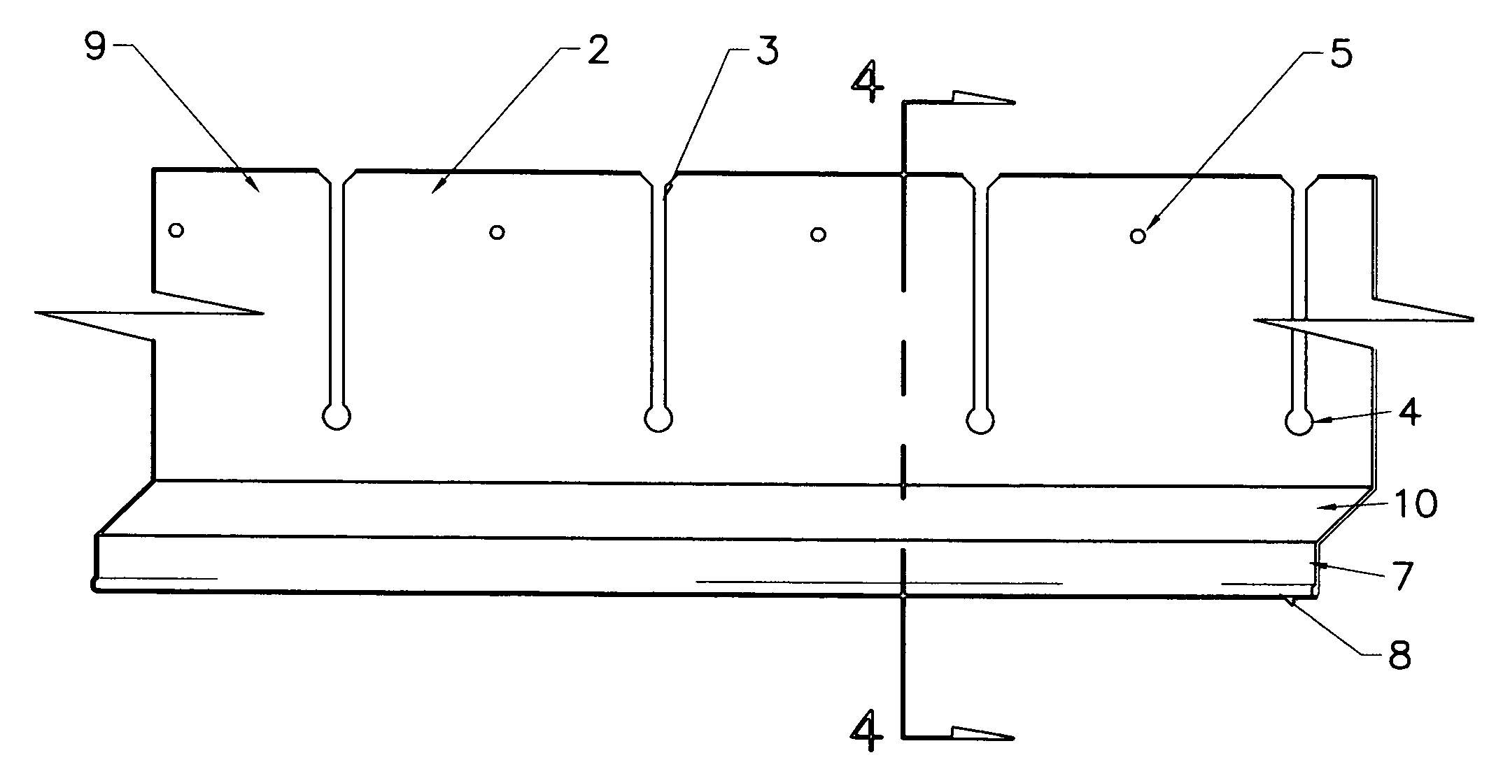
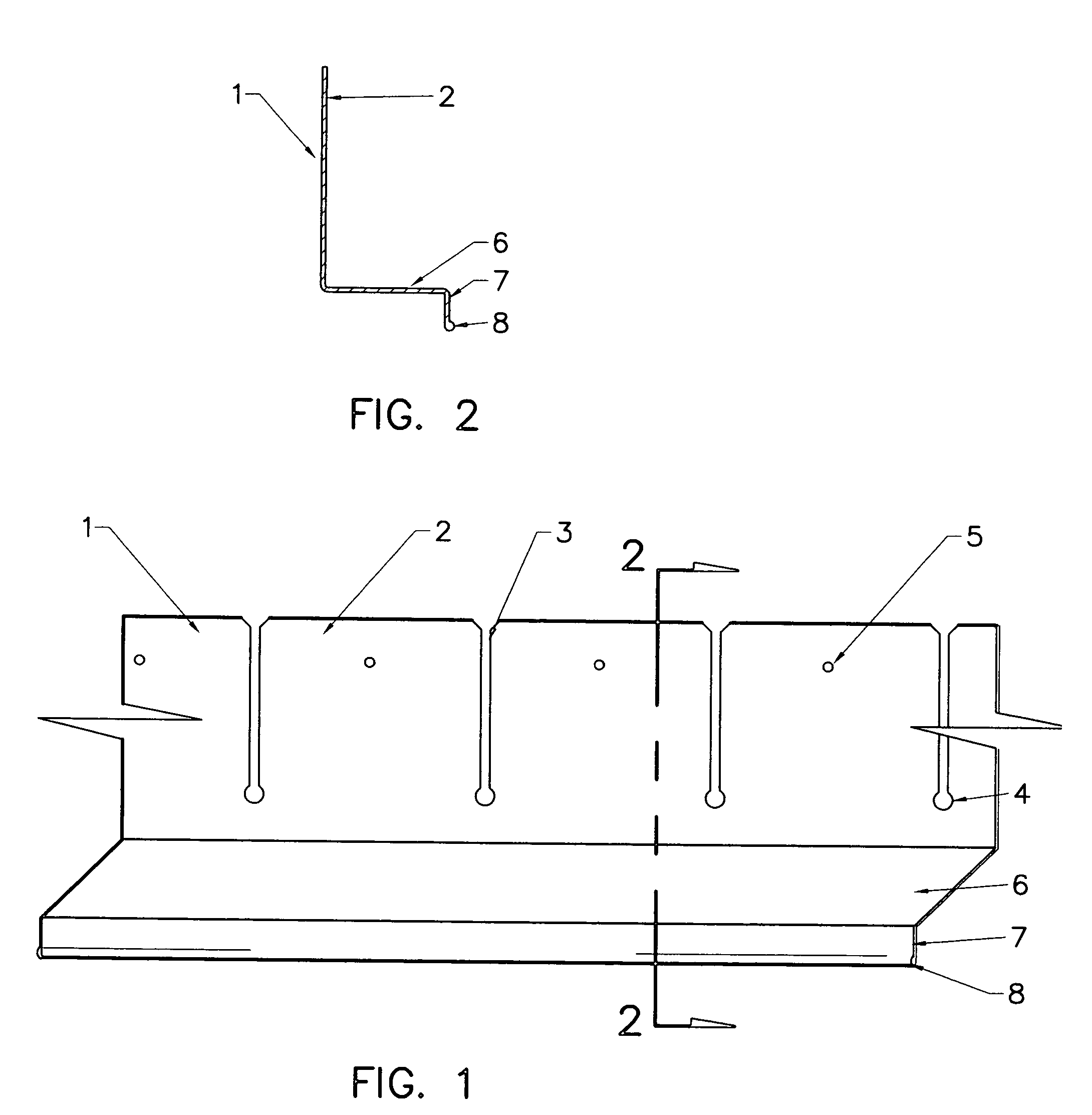
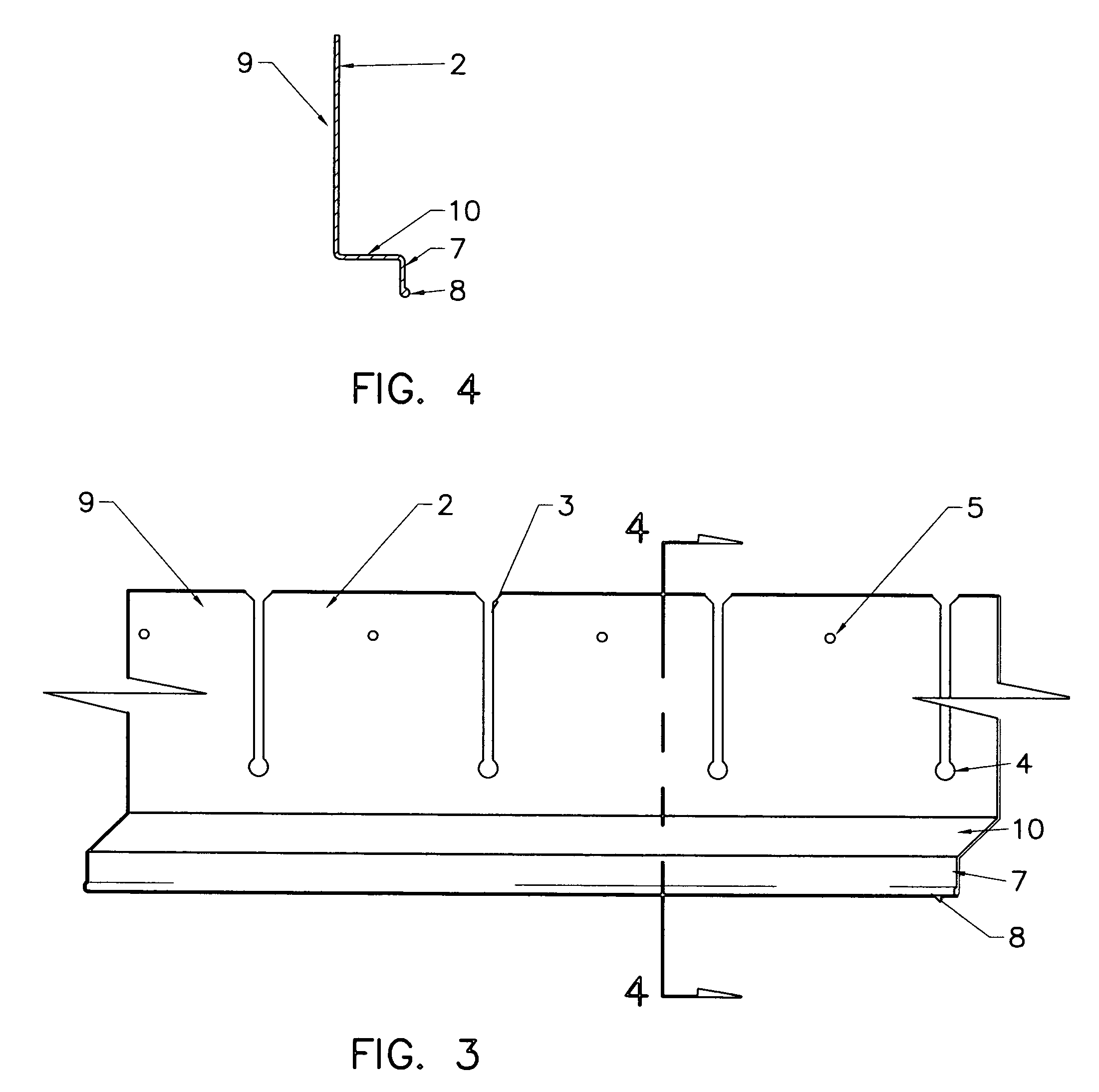
[0023]FIGS. 1-8 illustrate two embodiments of the present invention. FIGS. 1 and 2 indicate one embodiment, while FIGS. 3 and 4 show a second embodiment. FIGS. 5-8 show the bendable ‘Z’ head flashing integrated into different building components. Building components illustrated in FIGS. 5-8 characterize the use and installation of the present invention, but do not preclude use of bendable ‘Z’ head flashing with other building materials and construction components.

[0024]FIG. 1 is a oblique view of a portion of a novel bendable ‘Z’ head flashing 1. The rear vertical mounting flange 2 is shown with equally spaced notches 3. Each notch terminates in a circular void 4, being in proximity to the horizontal section, but maintaining a distance to provide a small section of uninterrupted vertical flange adjacent to the horizontal flange. When the horizontal leg 6 is curved during installation to conform to a radius, notches 3 will uniformly spread apart along the upper free edge of vertical ...


PUM


Abstract

Bendable ‘Z’ Head flashing is used in conjunction with other building materials above arched openings or components in the exterior walls of buildings to protect the building structure from water intrusion. Pre-formed notches in the vertically mounting flange allow the horizontal portion of the flashing to conform to arched or curved openings, the head of arch top window or door frames, and arched trim.

Description

CROSS REFERENCE TO RELATED APPLICATIONS AND DISCOSURES[0001]This non-provisional utility patent application claims the benefit of provisional patent application No. 60 / 756,646 filed Jan, 6, 2006, and disclosure document number 545447.BACKGROUND OF THE INVENTION[0002]The present invention relates to architectural stock flashing material used for weatherproofing the head of arch top windows and doors, and arched trim on the exterior buildings in building construction.[0003]In construction it is customary to install head flashing at the tops of openings in exterior walls, during the installation of windows, doors, and adjacent siding and trim. Uniform building codes require exterior openings exposed to the weather shall be flashed in such a manner to make them weatherproof. The intent is to keep moisture on the surface of building paper from wetting structural elements or entering the exterior wall cavity. Various flexible flashings, water resistant papers and sealants are utilized to ...

Claims


Application Information

Patent Timeline
IPC IPC(8): E04D13/14
CPCE04D13/1415E06B1/006E04F2013/061E06B2001/628E06B1/62
Inventor GAWOSKI, DOUGLAS S.
Owner GAWOSKI DOUGLAS S
Why Eureka
Try Eureka