[0013] One
advantage of the invention is to off-load the complexities in the tooling arrangements and add them as features to the
machine. Off-loading the tooling complexities to the press has three distinct advantages: (1) changes in tooling operation can be made by adjusting the program, not by expensive tooling modifications, (2) the
material flow can be modified in a number of ways for a given set of tools, and (3) the overall cost of the tooling is less since there is no need for costly specialized adapters. These factors can reduce the development time and cost associated when launching new products.
[0014] Thus, the invention provides a method for coining or forging a part having a wall with an inside
diameter. In one form, the part is a
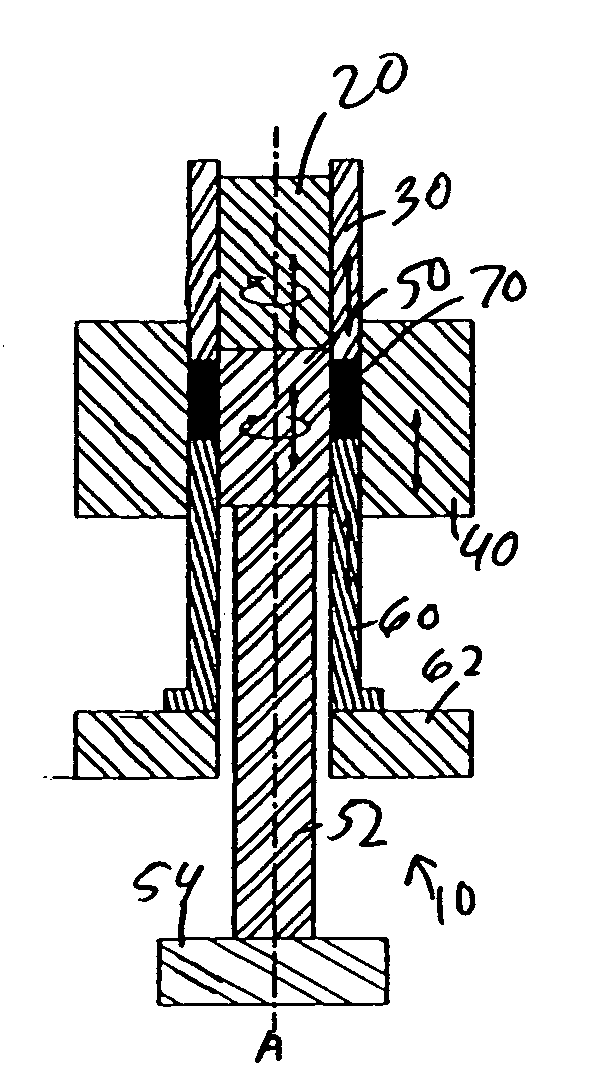
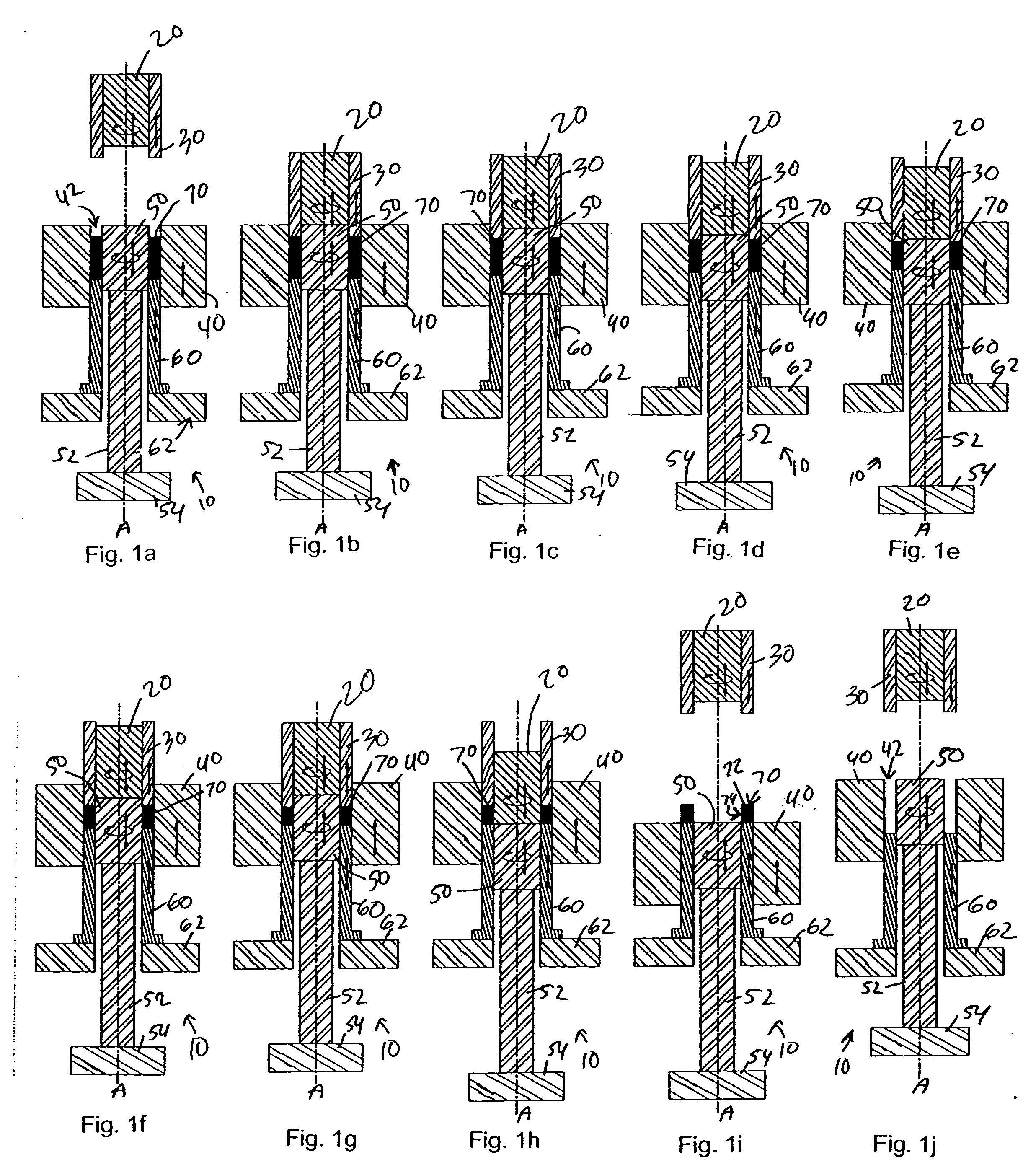
powder metal part. The method uses a press including a first rod, a first ram surrounding the first rod, a die plate having a die cavity, a second rod opposite the first rod, and a second ram surrounding the second rod wherein the first rod and the second rod are dimensioned to fit within the inside diameter of the part. In the method, the part is positioned within the die cavity, one of the first rod and the second rod is located as a core rod within the inside diameter of the part, and at least one of the first ram and the second ram is moved toward the other of the first ram and the second ram such that both the first ram and the second ram contact and
coin or
forge the wall of the part. The one of the first rod and the second rod acting as the core rod is then ejected from the inside diameter of the part by pushing the one of the first rod and the second rod acting as the core rod with the other of the first rod and the second rod.
[0015] In one version of the method, the first rod is a lower rod, the second rod is an upper rod, the first ram is a lower ram, and the second ram is an upper ram. The first ram and the second ram are dimensioned to fit within the die cavity, and the first ram and the second ram both move toward each other such that both the first ram and the second ram contact and
coin or
forge the wall of the part.
[0016] In another version of the method, the first rod is a lower rod, the second rod is an upper rod, the first ram is a stationary lower ram, and the second ram is an upper ram. The first ram and the second ram are dimensioned to fit within the die cavity, and the second ram moves toward the first ram such that both the first ram and the second ram contact and coin or forge the wall of the part.
[0017] In yet another version of the method, the part has an outwardly extending
flange on an end of the part. In this version of the method, the first rod is a lower rod, the second rod is an upper rod, the first ram is a stationary lower ram, and the second ram is an upper ram having an outside diameter substantially equal to an outside diameter of the
flange. The first ram and the second ram are dimensioned to fit within the die cavity, and the second ram moves toward the first ram such that both the first ram and the second ram contact and coin or forge the wall of the part.
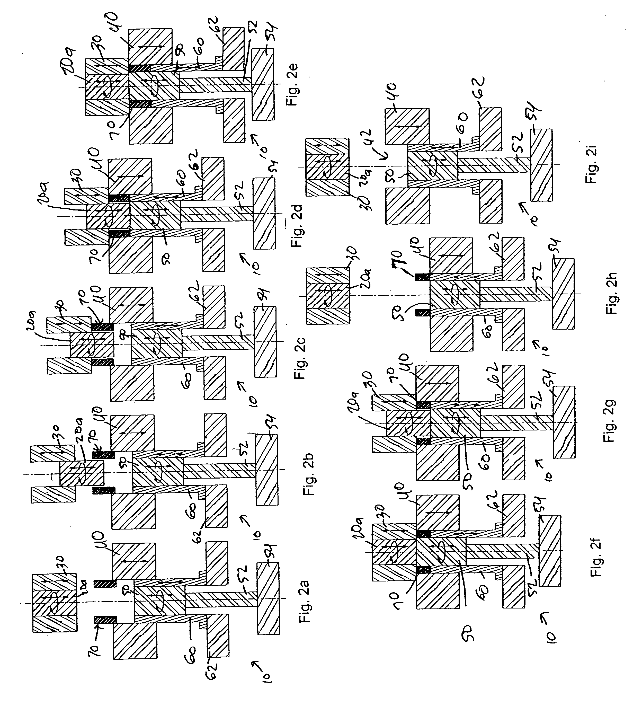
[0018] In still another version of the method, the part is a gear having an inside surface with
helical teeth. In this version of the method, the first rod is the core rod, the first rod is rotatable, and the first rod has an outer surface with
helical ribs dimensioned to be slidingly complementary to the
helical teeth of the gear. In this version of the method, the first rod is oscillated within the gear before ejecting the first rod from the gear in order to rotary burnish the helical teeth of the gear.

