Method of predicting the aerodynamic behavior of an aircraft element

Inactive Publication Date: 2014-03-18
AIRBUS OPERATIONS SAS
View PDF0 Cites 0 Cited by
  • Summary
  • Abstract
  • Description
  • Claims
  • Application Information

AI Technical Summary

Benefits of technology

[0031]The invention is intended to overcome these drawbacks by proposing a method for predicting the aerodynamic performance of an aircraft element with moving surface(s), using a structu

Problems solved by technology

The form of the aircraft element to be studied may make modeling thereof particularly complex.
The step of meshing of such an aircraft element is particularly delicate.
The difficulty is accentuated by the fact that the high-lift devices are both detached from and close to the rest of the wing group.
Moreover, the computations carried out on an unstructured meshing generally are longer.
It so happens that the precision with which the aerodynamic data are estimated has a direct impact on the weight of the aircraft.
Thus for example, insufficiently precise results make it necessary, for safety, to oversize the moving surfaces in order to guarantee

Method used


Image

  • Method of predicting the aerodynamic behavior of an aircraft element
  • Method of predicting the aerodynamic behavior of an aircraft element

Examples


Example

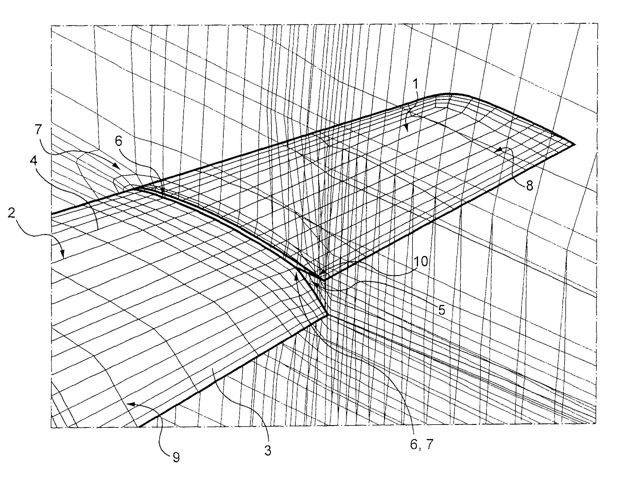
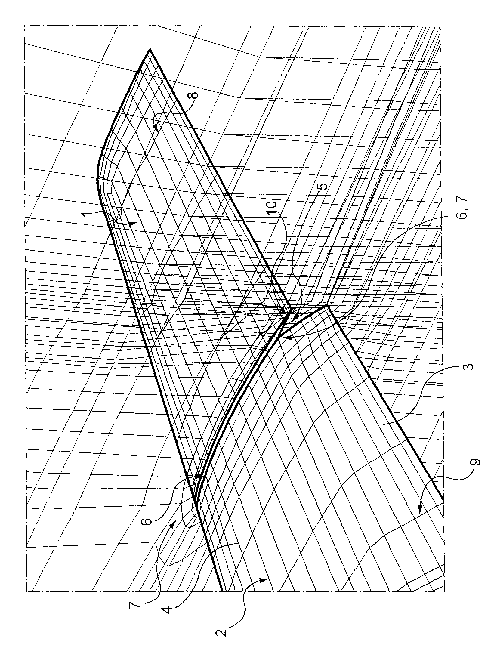
[0068]According to the invention, in order to predict the aerodynamic performance of an aircraft wing, one proceeds as follows.

[0069]In a first step, a digital form representative of the form that the wing assumes under predetermined operational and environmental conditions is prepared. The operational conditions to be determined prior to the implementation of the method according to the invention relate in particular to the deflection or non-deflection of the moving surfaces of the wing and the angles of deflection chosen, as the case may be.

[0070]On the attached FIGURE, a digital form representing an aircraft wing, created according to the invention, may be seen in part. On this digital form, a non-high-lift part 1 corresponding to an end section of the wing is perceived. It is to be noted that this end section in reality is equipped with a low-speed aileron. Nevertheless, under the predetermined conditions studied here, the low-speed aileron is in non-deflected position, so that ...


PUM


Abstract

A method for predicting the aerodynamic performance of an aircraft element under predetermined conditions, the aircraft element having at least one break at least partially separating two parts that cannot or should not be modeled with a common envelope form, in which: a digital form representative of the form that the aircraft element assumes under the predetermined conditions studied and in which each break is represented, is created, for each break, a totally non-coincident boundary surface at the joining of the two parts is created, and a partial structured meshing around each part is generated, the two partial meshings made in this way being independent of one another, and digital aerodynamic simulation computations using this meshing are carried out with the aid of an aerodynamic computation code capable of processing a totally non-coincident join.

Description

BACKGROUND OF THE INVENTION[0001]This invention relates to a method, implemented by computer, for predicting the aerodynamic performance of an aircraft or of a portion of an aircraft. Throughout the following, the phrase “aircraft element” designates, in the particular instance, a portion of an aircraft or an aircraft in its entirety.[0002]The invention applies to aircraft elements having at least one break, and more particularly—but not exclusively—to aircraft elements comprising at least one moving surface, such as a flap, wing flap, slotted flap, Fowler flap, slat, Kruger slat, retractable slotted flap, aileron, spoiler, rudder, elevator. . . .[0003]Predicting the aerodynamic performance of an aircraft element, and in particular of an aircraft element with moving surface(s), is essential in particular in order to make it possible to:[0004]calculate the loads sustained by the aircraft element and size the structure thereof accordingly and in optimized manner,[0005]size each moving...

Claims


Application Information

Patent Timeline
IPC IPC(8): G06F17/50
CPCG06F17/5095G06F2217/16G06F17/5018B64F5/00G06F30/15G06F30/23G06F2111/10
Inventor CALMELS, BENOIT
Owner AIRBUS OPERATIONS SAS
Why Eureka
Try Eureka