Ultrasonic sensor transmitting and receiving ultrasonic frequencies adjusted according to temperature

a technology of ultrasonic sensors and ultrasonic waves, which is applied in the direction of generators/motors, mechanical vibration separation, instruments, etc., can solve the problems of reducing the efficiency of ultrasonic sensor transmission or reception, and achieve the effect of improving the efficiency of ultrasonic sensor

Inactive Publication Date: 2007-07-12
DENSO CORP
View PDF4 Cites 30 Cited by
  • Summary
  • Abstract
  • Description
  • Claims
  • Application Information

AI Technical Summary

Benefits of technology

[0007]The present invention has been made in view of the above-mentioned problem, and an object of the present invention is to provide an improved ultrasonic sensor, efficiency of which is not adversely affected by the ambient temperature.

Problems solved by technology

Therefore, there is a problem that the transmitting or receiving efficiency of the ultrasonic sensor decreases as the ambient temperature deviates from a standard temperature.

Method used


Image

  • Ultrasonic sensor transmitting and receiving ultrasonic frequencies adjusted according to temperature
  • Ultrasonic sensor transmitting and receiving ultrasonic frequencies adjusted according to temperature
  • Ultrasonic sensor transmitting and receiving ultrasonic frequencies adjusted according to temperature

Examples


first embodiment

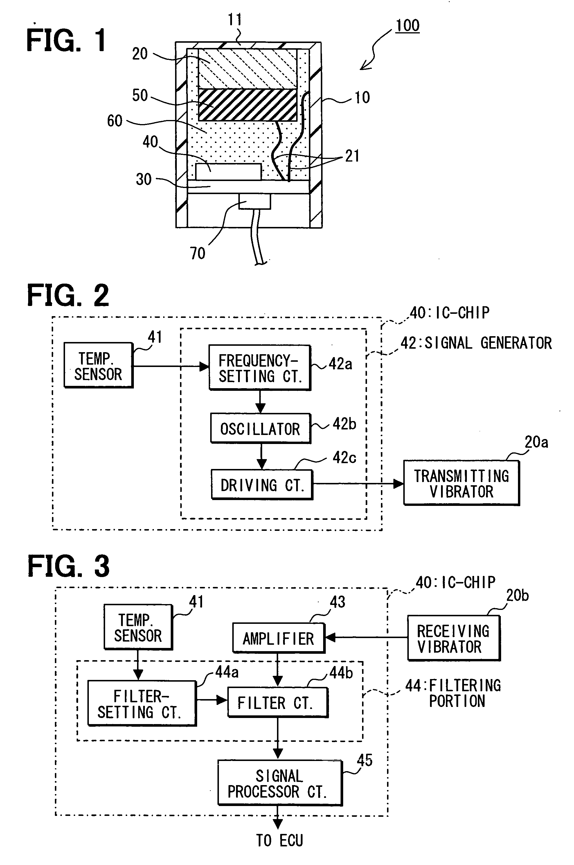
[0017]the present invention will be described with reference to FIGS. 1 and 2. As shown in FIG. 1, an ultrasonic sensor 100 is composed of a cylindrical casing 10 with a thin end wall 11 closing one end of the casing, a vibrator 20, an absorbing member 50, a vibration-absorbing material 60, an IC-chip 40 mounted on a printed circuit board 30, and a connector 70. The printed circuit board 30 is electrically connected to the vibrator 20 through lead wires 21.

[0018]The cylindrical casing 10 is made of synthetic resin, for example. One end of the cylindrical casing 10 is closed with the thin end wall 11. The vibrator 20 is made of, e.g., piezoelectric ceramics such as sintered PZT or barium titanate. The vibrator 20 is connected to the thin end wall 11 with adhesive, and electrodes of the vibrator 20 are connected to the printed circuit board 30 through the lead wires 21. A conductive thin film is formed on an inner surface of the casing 10, and one of the lead wires 21 is connected to ...

second embodiment

[0026]the present invention will be described with reference to FIG. 3. In this embodiment, the IC-chip 40 is constituted so that the ultrasonic sensor 100 functions as a receiver. Ultrasonic waves received by a receiving vibrator 20b via the end wall 11 are amplified by an amplifier 43, and then amplified signals having a frequency set in a filter are taken out through the filter. Since the resonant frequency of the end wall 11 changes according to the ambient temperature, the resonant frequency may become different from the frequency set in the filter. In this case, output signals of the ultrasonic sensor 100 become lower than expected. Namely, the receiving efficiency of the ultrasonic sensor 100 decreases.

[0027]This problem is overcome in the IC-chip 40 shown in FIG. 3. The IC-ship 40 includes a temperature sensor 41, an amplifier 43, a filtering portion 44 for selectively outputting signals having a frequency set in the filter, and a signal processor circuit 45. The same temper...

third embodiment

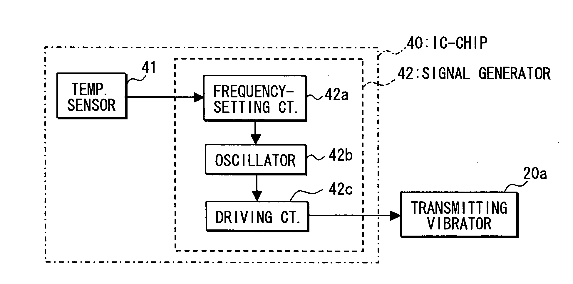
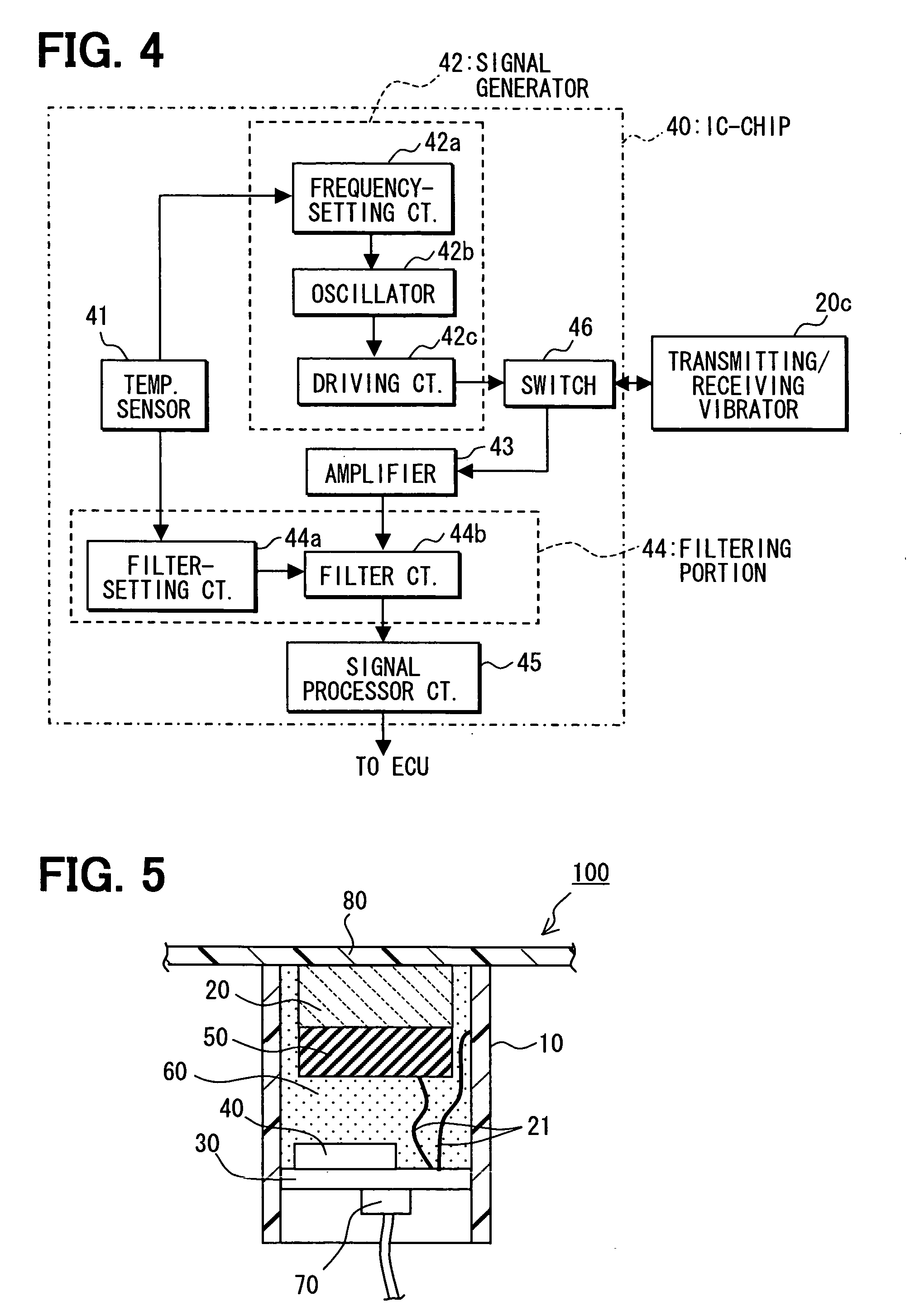
[0031]The third embodiment structured as above operates in the following manner. In transmitting operation, the frequency-setting circuit 42a sets the frequency that matches the resonant frequency of the end wall 11 based on the ambient temperature. The oscillator 42b feeds pulse signals having the set frequency to the driving circuit 42c. The driving circuit 42c feeds driving signals to the transmitting and receiving vibrator 20c through the switch 46. The transmitting and receiving vibrator 20c vibrates at the resonant frequency of the end wall 11. Thus, the ultrasonic waves are sent out from the end wall 11.

[0032]In receiving operation, the filter-setting circuit 44a sets the frequency (or a frequency region) to be selected in the filter circuit 44b, based on the ambient temperature detected by the temperature sensor 41. The frequency to be selected is set to match the resonant frequency of the end wall 11 at a present ambient temperature. Signals received from the transmitting a...


PUM

PropertyMeasurementUnit
frequencyaaaaaaaaaa
temperatureaaaaaaaaaa
resonant frequencyaaaaaaaaaa

Abstract

Components of an ultrasonic sensor are contained in a cylindrical casing having an end wall closing one end of the casing. A vibrator such as a piezoelectric element is disposed in the casing in contact with the end wall. An integrated circuit chip that includes a signal generator, a filter device and a temperature sensor is contained in the casing. Vibrations generated in the vibrator are transferred to the end wall that transmits ultrasonic waves. Ultrasonic waves received by the end wall are converted into electrical signals in the vibrator. Frequency of the transmitting signals and a frequency region of the signals to be received are controlled according to the ambient temperature, so that they always coincide with a resonant frequency of the end wall which changes according to the ambient temperature. Thus, high transmitting/receiving efficiency is always realized, irrespective of the ambient temperature.

Description

CROSS-REFERENCE TO RELATED APPLICATION[0001]This application is based upon and claims benefit of priority of Japanese Patent Application No. 2006-1827 filed on Jan. 6, 2006, the content of which is incorporated herein by reference.BACKGROUND OF THE INVENTION[0002]1. Field of the Invention[0003]The present invention relates to an ultrasonic sensor transmitting and / or receiving ultrasonic waves having frequencies adjusted according to ambient temperature.[0004]2. Description of Related Art[0005]An example of an ultrasonic sensor is disclosed in JP-A-8-237796. The ultrasonic sensor includes a piezoelectric vibrator disposed in a cylindrical casing in contact with a thin end wall that closes one end of the cylindrical casing. In transmitting operation, the thin end wall vibrated by the piezoelectric vibrator transmits ultrasonic waves. In receiving operation, ultrasonic waves received by the thin end wall are transmitted to the piezoelectric vibrator and converted into electrical signal...

Claims


Application Information

Patent Timeline
Patent Type & Authority Applications(United States)
IPC IPC(8): G01H13/00G01N29/00
CPCB06B1/0261B06B2201/40B06B2201/55G10K9/122G01N29/24G01N29/326G01N29/348G01N29/225
Inventor ENDOU, NOBORU
Owner DENSO CORP
Why Eureka
Try Eureka