Check valve for fluid

a check valve and fluid technology, applied in mechanical equipment, transportation and packaging, functional valve types, etc., can solve the problems of leakage, complicated check valves, and inability to obtain sealing effects, and achieve the effect of improving sealing reliability

Inactive Publication Date: 2007-07-12
SUNONWEALTH ELECTRIC MACHINE IND
View PDF2 Cites 18 Cited by
  • Summary
  • Abstract
  • Description
  • Claims
  • Application Information

AI Technical Summary

Benefits of technology

[0008] An object of the present invention is to p...

Problems solved by technology

In other words, the sealing effect could not be obtained and leakage occurs when the flexible membrane 94 is shifted.
However, such a check valve is very complicated.
Further, the check valve can only be used for fluid with a pressure high enough to overcome the elastic...

Method used


Image

  • Check valve for fluid
  • Check valve for fluid
  • Check valve for fluid

Examples


Embodiment Construction

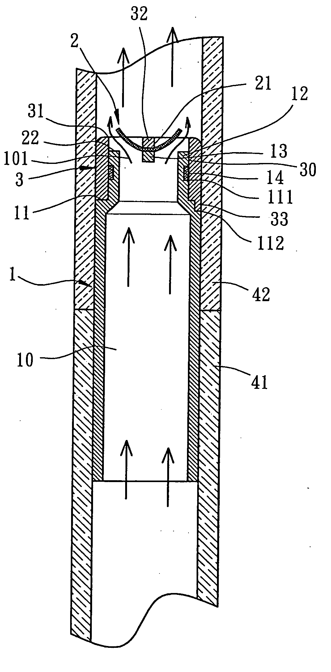
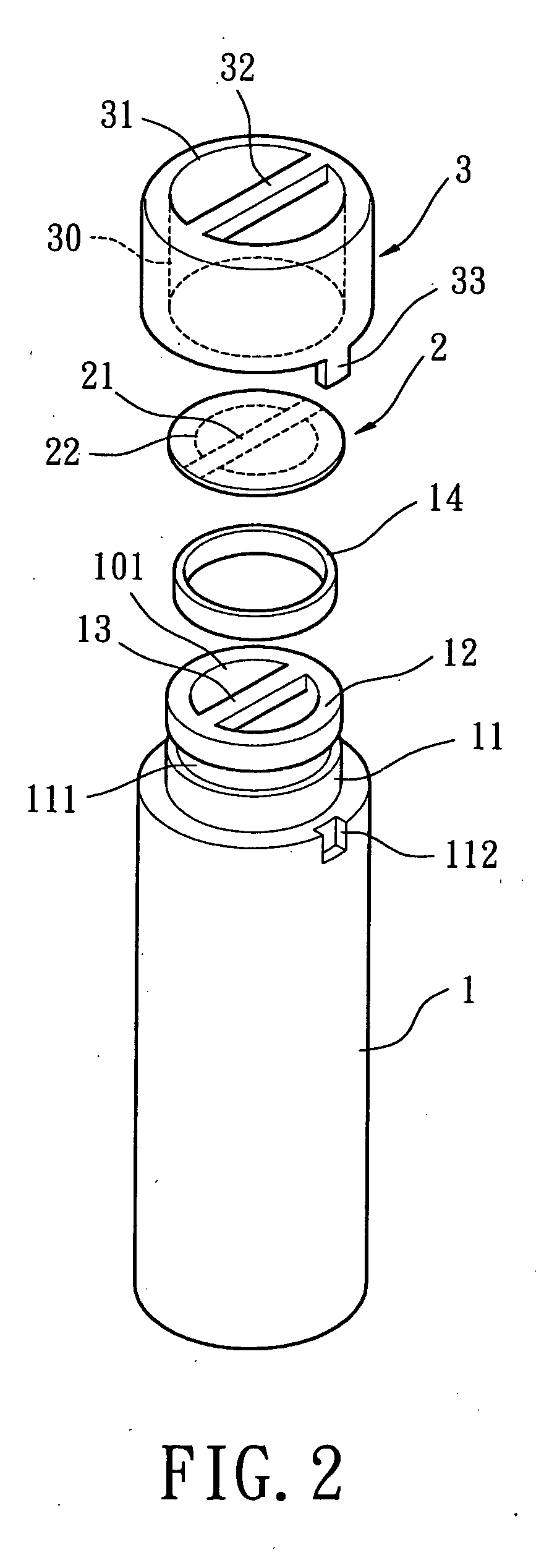
[0028] Referring to FIG. 2, a first embodiment of a check valve in accordance with the present invention comprises a tubular member 1, a flexible membrane 2, and a cap 3. The check valve allows fluid to flow in one direction (forward flow) and prevents the fluid to flow in the counter direction (counter flow). The check valve can be mounted on a pipeline of a fluid-cooling type heat-dissipating module for a personal computer or a notebook computer for controlling flow of the fluid for heat-dissipating purposes. The check valve can be used with other fluid mechanisms and operated in a similar way as disclosed above.

[0029] Referring to FIGS. 2 and 3, the tubular member 1 comprises a passageway 10, a coupling section 11 provided with an end face 12, a positioning rod 13, and a sealing washer 14. The passageway 10 extends throughout the tubular member 1 and includes a valve port 101 adjacent to the coupling section 11 and an inlet 102 in the inlet end of the tubular member 1. The coupl...


PUM


Abstract

A check valve for fluid includes a tubular member, a cap, and a flexible membrane. The tubular member includes a coupling section and an inlet. The coupling section of the tubular member includes a valve portion, an end face, and a positioning rod. The cap includes a coupling section coupled with the coupling section of the tubular member, an outlet aligned with the valve port, and a positioning rod on the outlet of the cap. The flexible membrane includes a positioning portion securely sandwiched between the positioning rods. The flexible membrane further includes a sealing circumference. When fluid flows in a reverse direction, the flexible membrane seals the valve port and the sealing circumference of the flexible membrane is supported by the end face of the tubular member. When the fluid flows in a forward direction, the flexible membrane is bent to allow the fluid to flow from the inlet to the outlet.

Description

BACKGROUND OF THE INVENTION [0001] 1. Field of the Invention [0002] The present invention relates to a check valve for fluid, and more particularly to a check valve having a reinforcing structure for a flexible membrane. [0003] 2. Description of Related Art [0004]FIG. 1 of the drawings illustrates a conventional check valve 91 for fluid. The check valve 91 is mounted between an inlet pipe 92 and an outlet pipe 93 and comprises a flexible membrane 94 having a fixed end 941 and a movable end 942. The fixed end 941 of the flexible membrane 94 is fixed to an end face of the inlet pipe 92. When the fluid flows from the inlet pipe 92 toward the outlet pipe 93, the movable end 942 of the flexible membrane 94 is pushed away from the end face of the inlet pipe 92, allowing fluid to flow to the outlet pipe 93. On the other hand, when the fluid flows from the outlet pipe 93 toward the inlet pipe 92, the movable end 942 of the flexible membrane 94 is pushed by the fluid to press against the end...

Claims


Application Information

Patent Timeline
IPC IPC(8): F16K15/14
CPCF16K15/148Y10T137/784
Inventor HORNG, ALEXYIN, TSO-KUO
Owner SUNONWEALTH ELECTRIC MACHINE IND
Why Eureka
Try Eureka