Ultrasound welding device

a welding device and ultrasonic technology, applied in the direction of mechanical work/deformation, layered products, lamination, etc., can solve the problems of insufficient relatively narrow welding seams that were insufficient for various applications, and fluctuation of the quality of formed seams, etc., to achieve low energy consumption and power peaks.

Inactive Publication Date: 2007-07-12
JENTSCHMANN ZURICH
View PDF3 Cites 21 Cited by
  • Summary
  • Abstract
  • Description
  • Claims
  • Application Information

AI Technical Summary

Benefits of technology

[0007] Furthermore the welding device according to the invention has low energy consumption. Power peaks may be avoided thanks to the closed-loop control in real time. One may also prevent changes in certain welding parameters during the welding procedure from leading to a change of the seam quality. The ultrasonic welding device according to the invention may e.g. be used for welding or bonding thermoplastic films or tarpaulin [covers] or of fabrics coated with thermoplasts such as PVC. Uncoated substances such as e.g. acrylic which is widely used in the manufacture of canopies may be connected without any problem by way of hot-melt adhesives Possible applications for example are the manufacture of films, canopies, tarpaulin [covers], pieces of clothing, etc.

Problems solved by technology

The evaluation of suitable parameter constellations with continuously operated ultrasonic welding installations is unequally more difficult than with cycled ones.
Furthermore, until now only relatively narrow welding seams could be formed which were insufficient for various applications.
One disadvantage of such conventional continuously operated welding installations lies in the fact that fluctuation of quality of the formed seams may occur.
Such seams in particular may have weak points at which the films are insufficiently welded to one another, but also regions, where the films e.g. are damaged or destroyed as a result of too great a development of heat.

Method used


Image

  • Ultrasound welding device
  • Ultrasound welding device
  • Ultrasound welding device

Examples


Embodiment Construction

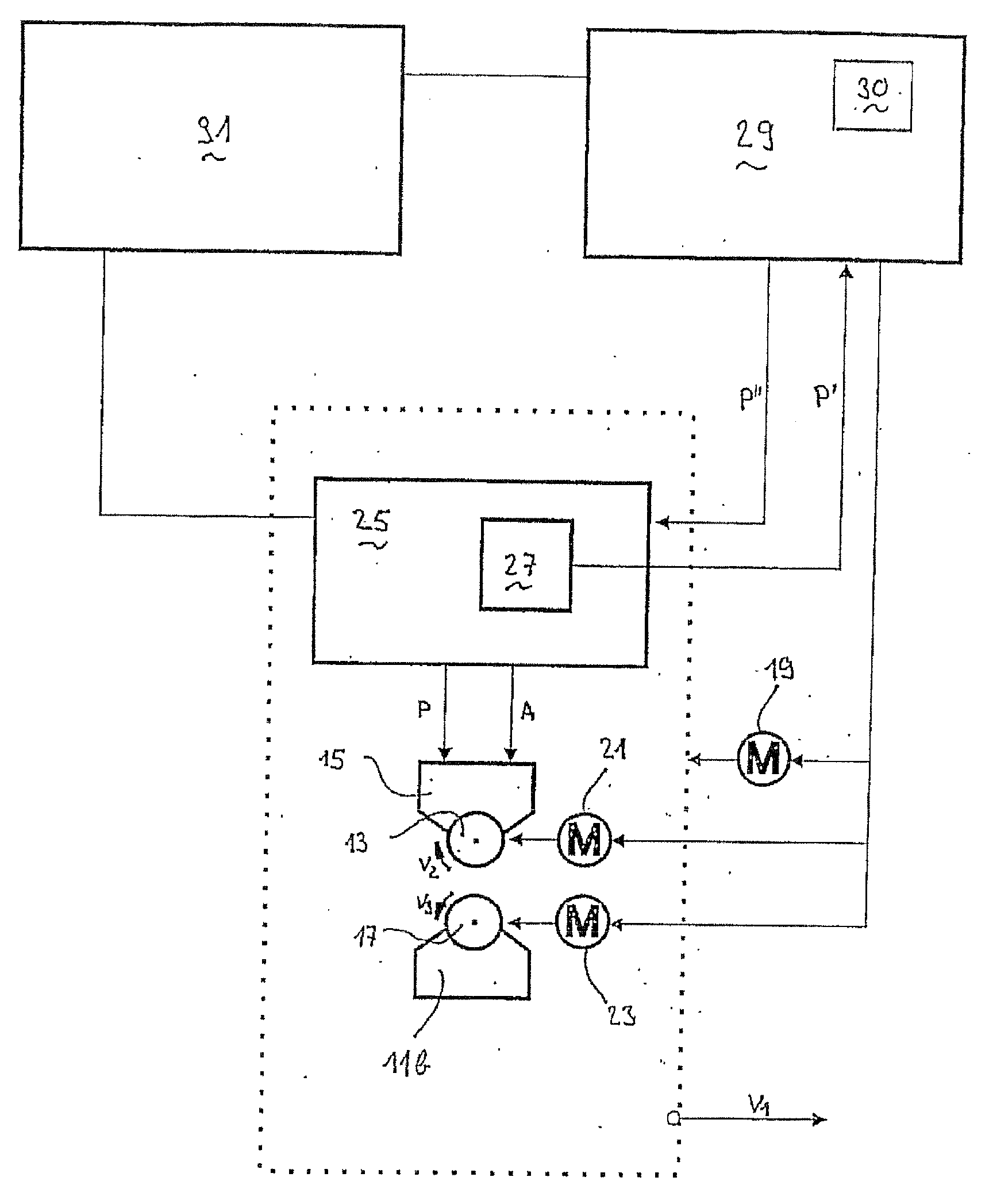
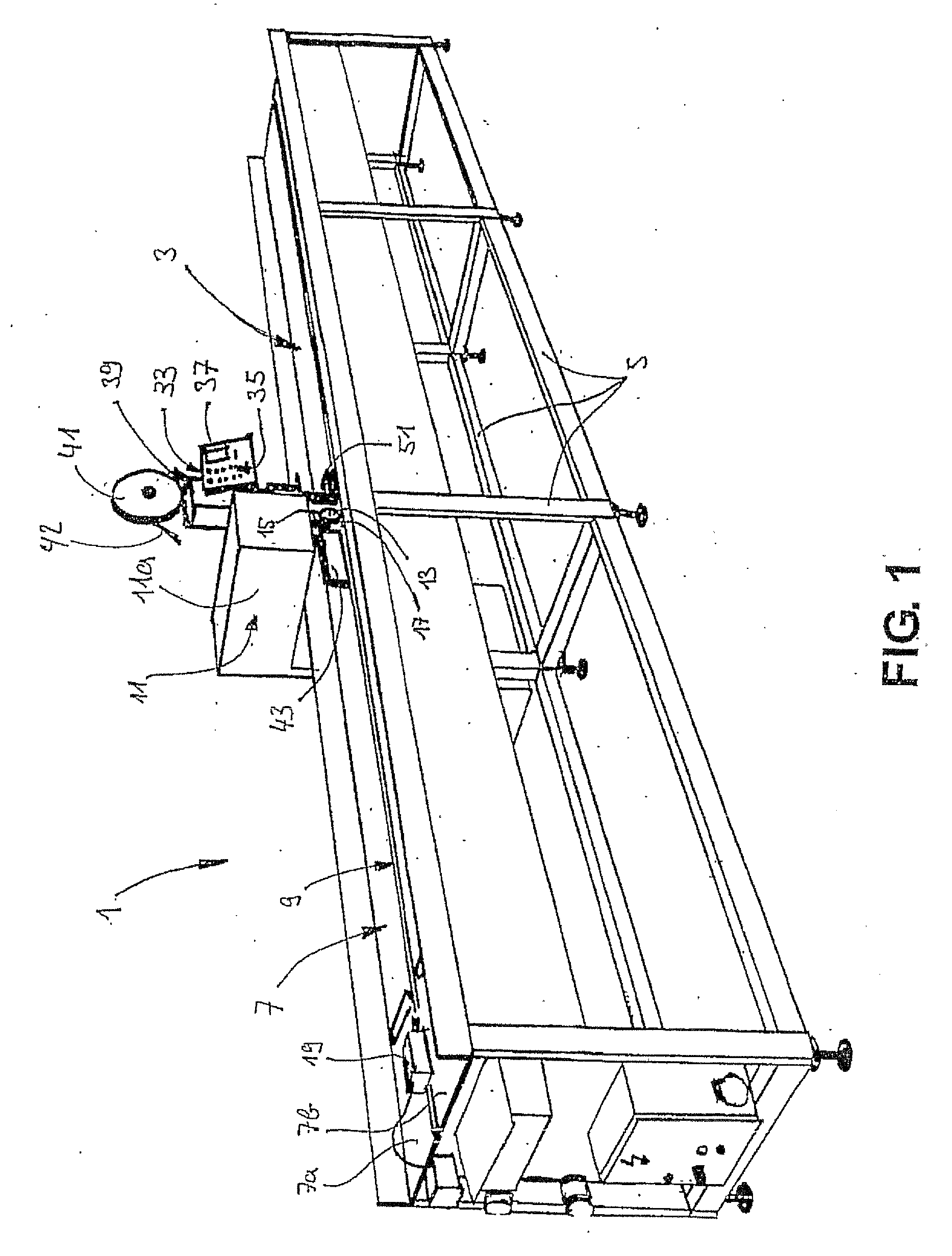
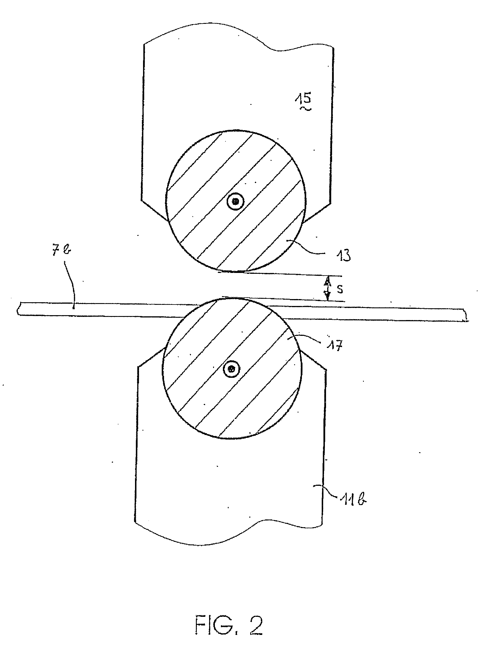
[0013]FIG. 1 in a schematic representation shows an ultrasonic welding device in a first design. The welding device 1 comprises the following elements (not a complete listing): [0014] A long working table with a stable framing 5 of aluminum profiles and a horizontal working plate 7 which centrally is divided into two part plates 7a, 7b by way of a gap 9 running in the longitudinal direction. [0015] An L-shaped or C-shaped carrier 11 which is displaceably guided on guide rails (not shown) in the longitudinal direction. [0016] A welding head with a wheel-like roller sonotrode, called sonotrode 13 for short, which is rotatably held on a sonotrode arm 15 over the gap 9. The welding head may be lowered or lifted in settable positions or attitudes along a guide (not shown) formed on the upper arm 11a, e.g. by way of a pneumatic drive. If the sonotrode 13 rests on a subject the contact pressure or the contact force may be detected e.g. by way of a pressure sensor. The contact pressure, ind...


PUM

PropertyMeasurementUnit
widthaaaaaaaaaa
seam widthsaaaaaaaaaa
widthaaaaaaaaaa

Abstract

The ultrasonic welding device (1) comprises a continuously operable roller sonotrode (13). The power of the roller sonotrode (13) may be closed-loop controlled depending on other welding parameter in a manner such that long welding seams or adhesive seam with a uniform quality may be manufactured. The method may be used for manufacturing canopies, tarpaulins, or pieces of clothing

Description

BACKGROUND OF THE INVENTION [0001] The subject-matter is an ultrasonic welding device, a method for operating an ultrasound welding device as well as subjects manufactured according to this method, according to the features of patent claims 1, 5 and 8. [0002] Ultrasonic welding is a joining technique with which e.g. thermoplastic or metallic subjects are connected to one another by supplying energy in the form of ultrasound or of high-frequency mechanical oscillation. A sonotrode which presses a first subject against a second subject is excited into oscillation in the ultrasonic range. By way of the transmission of the movement energy into the region of the border surface of both subjects, local frictional heat is produced which softens or melts the surfaces of the subjects and connects them together. [0003] Ultrasonic welding technology amongst other things is used for connecting thermoplastic films or fabric. Apart from devices for the cyclic welding with which the high-frequency ...

Claims


Application Information

Patent Timeline
Patent Type & Authority Applications(United States)
IPC IPC(8): B32B37/00B29C65/00B29C65/08B29C65/50
CPCB29C65/087Y10T156/1741B29C66/8242B29C66/83413B29C66/83421B29C66/83423B29C66/8362B29C66/872B29C66/90B29C66/9221B29C66/9241B29C66/92611B29C66/93451B29C66/939B29C66/949B29C66/9516B29C66/96B29K2027/06B29C65/5057B29C66/7292B29C66/1122B29C66/961B29C65/4815B29C66/93411B29C65/5021B29C65/5092B29C65/086B29C66/932B29C66/934B29C65/00B29C66/73921B29C66/43B29C66/71B29C66/845B29C66/86533B29K2033/08
Inventor HEIL, DIETMARBARTHOLDI, PIERRE
Owner JENTSCHMANN ZURICH
Why Eureka
Try Eureka