
Temporary stocking mechanism and printer

a technology which is applied in the field of temporary stocking mechanism and printer, can solve the problems of sheet material deflecting, the inability to apply temporary stocking mechanism according to the related art to a small mobile printer, and the increase in the size of the device as a whole, so as to improve the reliability of the operation of taking, improve the length of the sheet material, and improve the effect of the reliability of the operation

Inactive Publication Date: 2007-07-12
SEIKO INSTR INC
View PDF3 Cites 2 Cited by
  • Summary
  • Abstract
  • Description
  • Claims
  • Application Information

AI Technical Summary

Benefits of technology

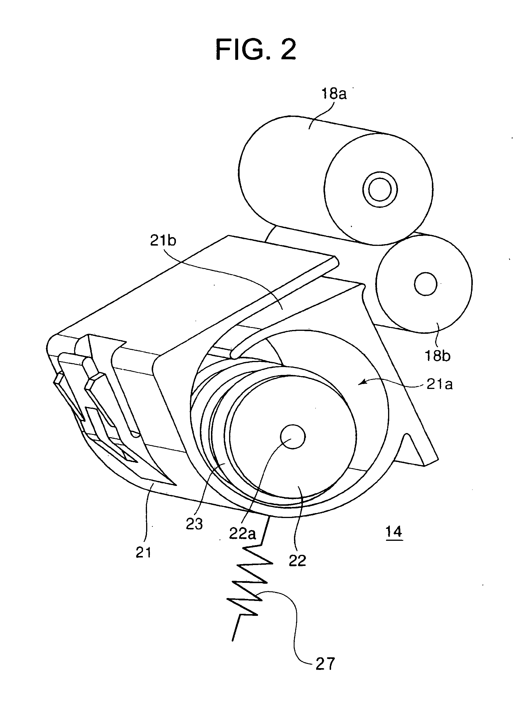
[0022] Further, the temporary stocking member of the temporary stocking mechanism according to the present invention is composed of a plurality of members which are combined with one another so as to be capable of being separated so that the take-up roller is exposed to the outside. With this construction, even in a case where a problem such as so-called paper jam occurs with respect to the sheet material to be taken up along the inner peripheral surface of the temporary stocking member as the take-up roller rotates, only the temporary stocking member is disassembled to expose the take-up roller to the outside, thereby making it possible to quickly solve the problem. Thus, workability in maintenance of the temporary stocking portion is improved.
[0024] As described above, according to the present invention, it is possible to down-size the temporary stocking member, improve reliability of an operation of taking up the sheet material, enable the sheet material to be smoothly taken up in the take-up space of the temporary stocking member, and increase a length of the sheet material to be taken up in the take-up space of the temporary stocking member.

Problems solved by technology

As a result, there arises a problem in that in order to stock the sheet material, it is required to prepare a large space.
Further, there is also a problem in that an enlargement of the space for stocking the sheet material causes an increase in. size of the device as a whole.
Accordingly, the temporary stocking mechanisms according to the related art cannot be applied to a small mobile printer which can be easily carried with one hand.
As a result, it is difficult to transmit a force of the transport rollers with which the sheet material is pushed in a lengthwise direction of the sheet material, thereby causing the sheet material to be deflected at a midpoint thereof.
That is, with regard to the temporary stocking portion described above, there is a fear that the sheet material cannot be smoothly taken up in the take-up space depending on a level of rigidity, that is, a so-called elasticity of the sheet material itself.
In particular, there is a problem in that when a sheet material having a relatively small width of about 30 mm is used, the level of elasticity of the sheet material itself is low, so the sheet material is caused to -buckle while being taken up in the take-up space, so satisfactory rolling cannot be achieved.
Therefore, the leading edge suffers a relatively large damage due to the heat-sensitive adhesive layer.
Accordingly, there is a problem in that an operation of taking up the sheet material stops, so the sheet material is not satisfactorily taken up in the take-up space, therefore a length of the sheet material capable of being taken up in the take-up space is short.
However, when the guide portion is molded to be integral with the temporary stocking member, a radius of curvature of the guide portion is smaller than a radius of curvature of an inner peripheral surface of the temporary stocking member, so a transportation load of the sheet material increases.
Therefore, by molding the guide portion integrally with the temporary stocking member, there is a disadvantage in that a length of the sheet material to be taken up, that is, an amount of the sheet material which can be taken up is reduced.

Method used


Image

  • Temporary stocking mechanism and printer
  • Temporary stocking mechanism and printer
  • Temporary stocking mechanism and printer

Examples


first embodiment

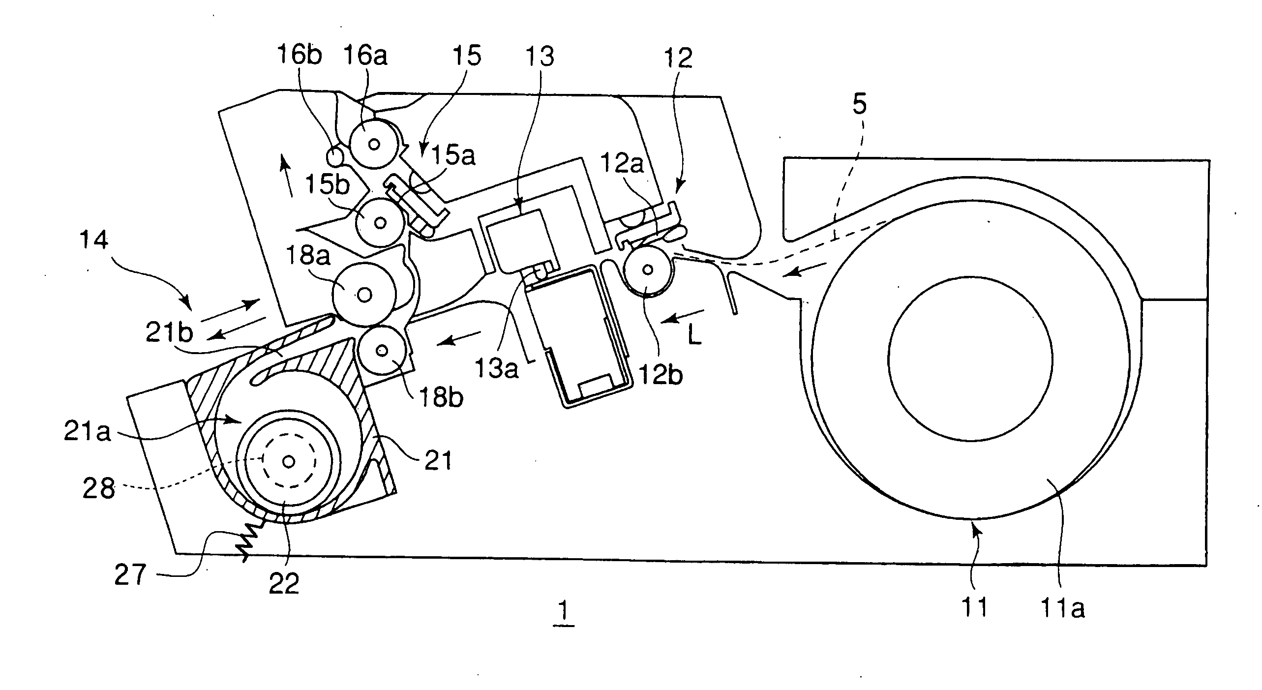
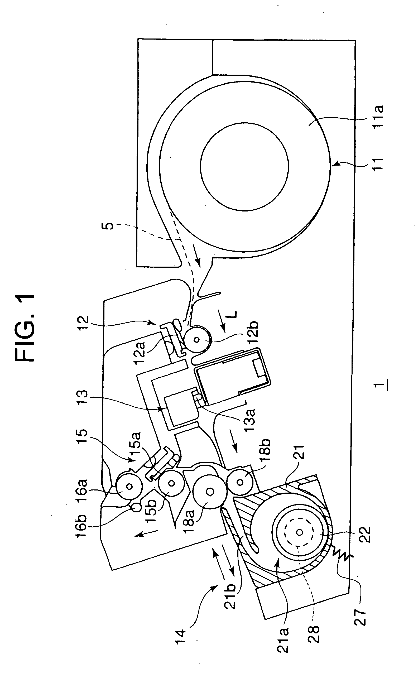
[0032] As shown in FIG. 1, a label issuing device 1 according to a first embodiment of the present invention includes a sheet supply portion 11 for supplying a sheet material 5 along a transport direction of the sheet material 5 indicated by arrows L of FIG. 1, a printing portion 12 for printing various kinds of information in a form of characters or the like on a heat-sensitive printing layer of the sheet material 5, a cutting portion 13 for cutting the sheet material 5 on which printing is effected by the printing portion 12 into a predetermined length, a temporary stocking portion 14 for temporarily stocking the sheet material 5 on which printing is effected by the printing portion 12, a thermal activation portion 15 for thermally activating a heat-sensitive adhesive layer of the sheet material 5 supplied from the temporary stocking portion 14, and a pair of discharge rollers 16a and 16b for discharging the sheet material 5 to the outside the device.

[0033] The sheet supply porti...

second embodiment

[0053] Next, with reference to the drawings, a description is made of a label issuing device according to a second embodiment of the present invention, including another temporary stocking portion. The label issuing device of the second embodiment has a basic structure, except a part of the temporary stocking portion, which is the same as that of the label issuing device 1 according to the first embodiment. The same members are denoted by the same reference symbols and the descriptions thereof are omitted.

[0054] As shown in FIGS. 3 and 4, a temporary stocking portion 34 including a label issuing device 2 according to the second embodiment includes a driven roller 35 serving as a press-contact member, which is brought into press contact with a peripheral surface of the take-up roller 22, and a coil spring 37 serving as a press-contact means for causing a peripheral surface of the driven roller 35 to be pressed against the peripheral surface of the take-up roller 22.

[0055] A part of...


PUM

PropertyMeasurementUnit
widthaaaaaaaaaa
lengthaaaaaaaaaa
inner diameteraaaaaaaaaa

Abstract

A printer is provided with a printing means for effecting printing on a sheet material, and a temporary stocking mechanism for temporarily stocking the sheet material on which printing is effected. The temporary stocking mechanism is provided with a temporary stocking member having a cylindrical take-up space in which the sheet material is taken up, for temporarily stocking the sheet material on which printing is effected by a printing means, a take-up roller provided in the take-up space, for taking up the sheet material, a driving means for rotationally driving the take-up roller, and a press-contact means for bringing a peripheral surface of the take-up roller into press contact with an inner peripheral surface of the temporary stocking member.

Description

[0001] This application claims priority to Japanese Patent Application No. 2006-004641 filed Jan. 12, 2006, the entire content of which is hereby incorporated by reference. BACK GROUND OF THE INVENTION [0002] The present invention relates to a temporary stocking mechanism for temporarily stocking a sheet material by taking up the sheet material on which printing is effected and a printer equipped with the temporary stocking mechanism. [0003] As a label used while being affixed to a product, there is proposed a label issued from a sheet material obtained by providing a printing layer to one surface of a sheet-like base material and a heat-sensitive adhesive layer to the other surface thereof. [0004] In general, a printer for effecting printing on the label having the heat-sensitive adhesive layer includes a sheet supply device for supplying the sheet material, a printing device for printing various kinds of information on the printing layer of the sheet material supplied from the she...

Claims


Application Information

Patent Timeline
Patent Type & Authority Applications(United States)
IPC IPC(8): B65H5/00
CPCB41J3/4075B65H2701/192B41J11/70B41J13/0045B41J13/03B65C11/0289B65C11/066B65C2009/005B65H5/28B65H29/008B65H2301/4193B65H2404/694B65H2601/11B65H2601/422B65H2601/523B41J11/002B41J11/0024
Inventor KOHIRA, HIROYUKI
Owner SEIKO INSTR INC
Learn More