Telescope with variable magnification

a telescope and magnification technology, applied in the field of zooming telescopes, can solve the problems of limiting the field of vision, deteriorating image quality, and inability to provide an inversion system

Inactive Publication Date: 2007-07-12
CARL ZEISS SPORTS OPTICS
View PDF16 Cites 13 Cited by
  • Summary
  • Abstract
  • Description
  • Claims
  • Application Information

AI Technical Summary

Benefits of technology

[0022] This measure has the advantage that the stopping off of the s

Problems solved by technology

This results in a deterioration of the image quality.
Obviously an inversion system is not provided in these objective lenses.
A field stop, however, in contrast to an ap

Method used


Image

  • Telescope with variable magnification
  • Telescope with variable magnification
  • Telescope with variable magnification

Examples


Embodiment Construction

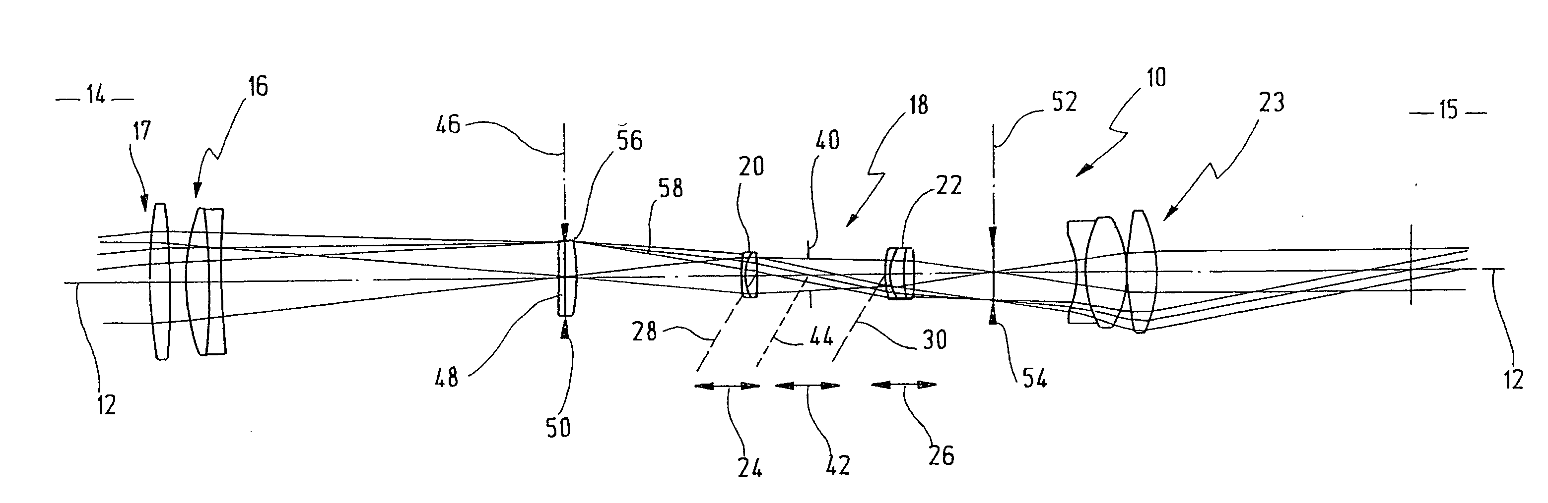
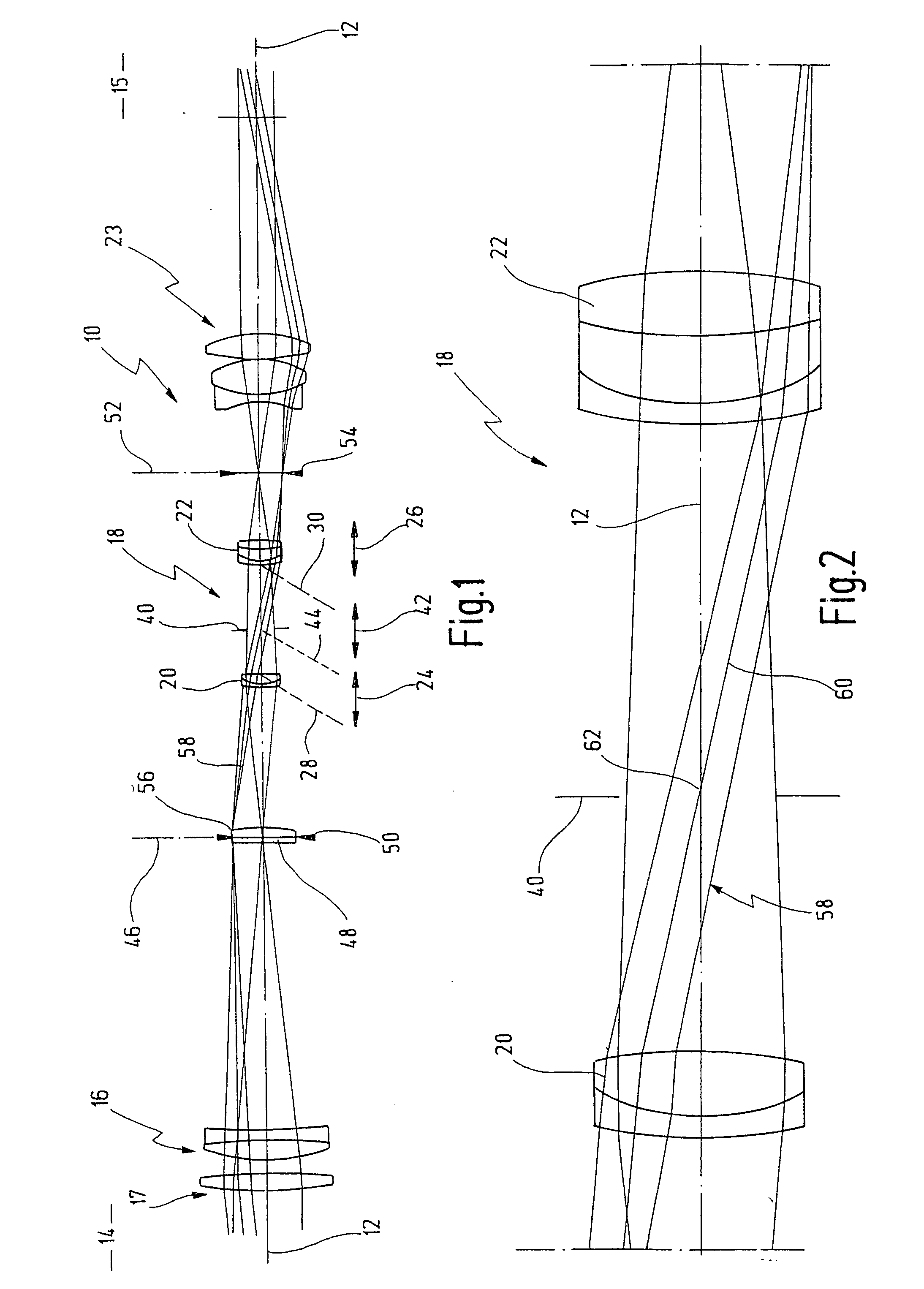
[0032] In FIG. 1, reference numeral 10 as a whole designates an embodiment of a telescope according to the present invention being schematically illustrated with its ray path. Telescope 10 has an optical axis 12. In FIG. 1 the object side 14 is shown left and the image side 15 is shown right.

[0033] On object side 14 one can see an objective lens 16 which, as the case may be, may be provided with an objective lens aperture stop 17 or may configure same itself.

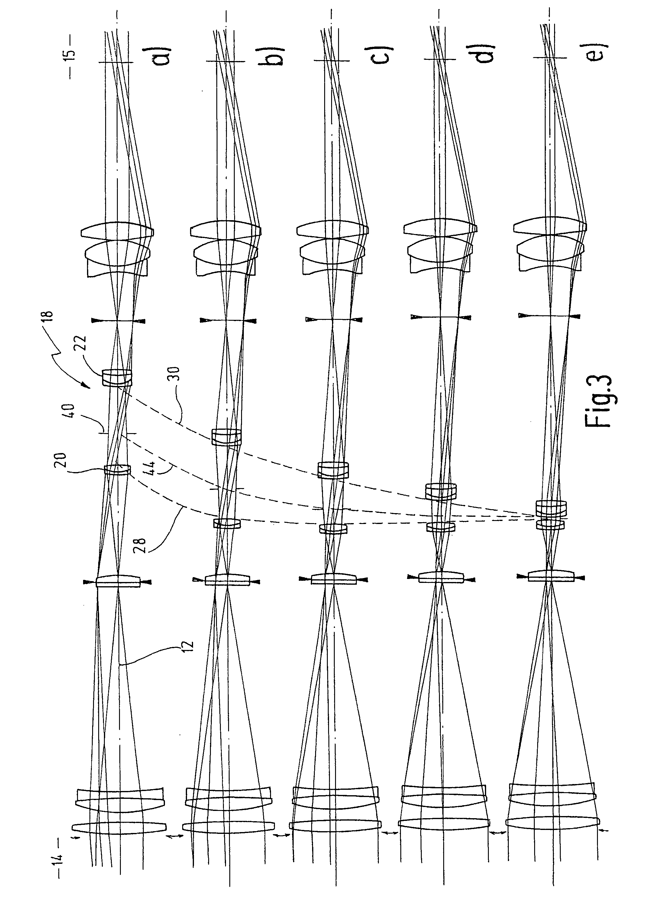
[0034] On the right hand side next to objective lens 16 an inversion system 18, also referred in the art as erection system, with variable magnification is shown on optical axis 12. It is, therefore, a system which combines in itself both functions, namely a variable magnification and an image inversion.

[0035] Inversion system 18 is provided with a first lens group 20 as well as with a second lens group 22 arranged at a predetermined axial distance with respect to one another.

[0036] Finally, there is still an eyepiece 23 arr...


PUM


Abstract

A telescope has an optical axis. As seen from an object side, there are provided along the optical axis an objective lens, two lens groups adapted to be shifted along the optical axis independently from one another and having together a variable magnification, an inversion system, and an eyepiece. An aperture stop is provided between the lens groups, and the aperture stop is adapted to be shifted along the optical axis as a function of the axial position of the lens groups.

Description

FIELD OF THE INVENTION [0001] The invention is related to the field of telescopes having a variable magnification, also referred to as zooming telescopes. [0002] More specifically, the invention is related to the field of telescopes having an optical axis, wherein, as seen from an object side, there are provided along an optical axis an objective lens, two lens groups adapted to be shifted along the optical axis independently from one another and having together a variable magnification, an inversion system, and an eyepiece. BACKGROUND OF THE INVENTION [0003] German disclosure document DE 10 2004 001 481 A1 describes a telescope which, as seen from the object side, is provided with an objective lens, a zooming system consisting of two lens groups, a prism inversion system, and an eye-piece. The telescope is relatively long. No special measures are taken in this telescope for the protection against stray light. [0004] Moreover, U.S. Pat. No. 5,973,861 also discloses telescopes with v...

Claims


Application Information

Patent Timeline
IPC IPC(8): G02B17/00G02B23/00G02B21/00
CPCF41G1/38G02B15/163G02B23/16G02B23/00G02B23/145G02B15/167G02B15/144
Inventor WAGNER, THOMASTAUTZ, VOLKER
Owner CARL ZEISS SPORTS OPTICS
Why Eureka
Try Eureka