Exhaust gas diffuser of a gas turbine

Inactive Publication Date: 2013-07-04
SIEMENS AG
View PDF6 Cites 5 Cited by
  • Summary
  • Abstract
  • Description
  • Claims
  • Application Information

AI Technical Summary

Benefits of technology

[0008]As a result of the pitched orientation of the guide elements (pitch) in relation to the center axis, both an exceptionally efficient and space-saving construction for de-swirling of the flow is disclosed. The pitch of the spiral line is comparatively large in this case so that the spiral lines are only slightly inclined in relation to the center axis of the exhaust gas diffuser. The pitch can also become smaller along its extent. Preferably, it increases, however, in order to obtain an outflow from the exhaust gas diffuser which has as little swirl as possible. This arrangement is particularly advantageous in the case of an axial exhaust gas diffuser in which the number of guide elements is the same as a number of support struts which are provided in the exhaust gas diffuser or directly upstream thereof for the turbine-side support of the gas turbine rotor.
[0009]In an advantageous embodiment, the guide body has a cross-sectional contour which is arranged perpendicularly to the center axis of the exhaust gas diffuser and which is in the shape of a star, the points of which are formed by the respective guide elements. By means of the star-shaped cross-sectional contour, significantly greater rigidity of the inner wall of the exhaust gas diffuser, now formed as an annular diffuser, can be achieved. The tendency of the guide body towards vibrating on account of the flow is significantly reduced as a result. Consequently, it is also possible to design the guide body in a way in which it is fastened on only one side so that its end facing the diffuser outlet overhangs in the exhaust gas diffuser in a freely suspended manner. An aerodynamically disturbing and cost-increasing outlet-side support of the guide body can consequently be avoided on account of the greater rigidity of the guide body.
[0010]In an expedient development, each guide element has an outer tip which projects radially outward from the center axis of the exhaust gas diffuser, the shortest distance of which to the center axis (that is to say in the cross section arranged perpendicularly to the center axis) reduces with decreasing axial distance to the diffuser outlet. In this case, each recess has a radially inward disposed base, the shortest distance of which to the center axis (that is to say in the cross section arranged perpendicularly to the center axis) also reduces with decreasing axial distance to the diffuser outlet. As a result of this, a widening of the flow cross section of the exhaust gas dif

Problems solved by technology

It is disadvantageous, however, that the guide body is comparatively long and therefore has to be supported by additional

Method used


Image

  • Exhaust gas diffuser of a gas turbine
  • Exhaust gas diffuser of a gas turbine
  • Exhaust gas diffuser of a gas turbine

Examples


Embodiment Construction

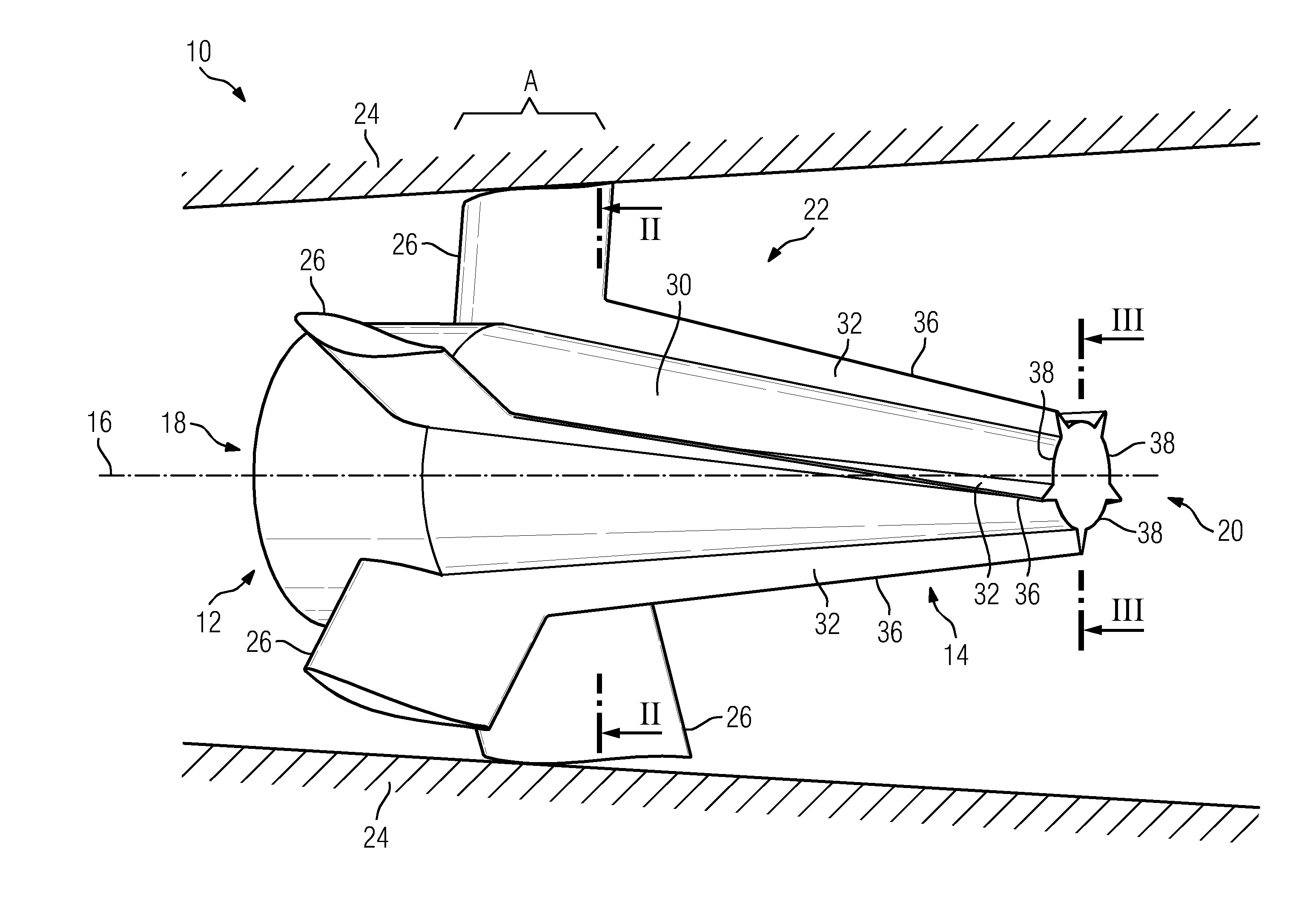
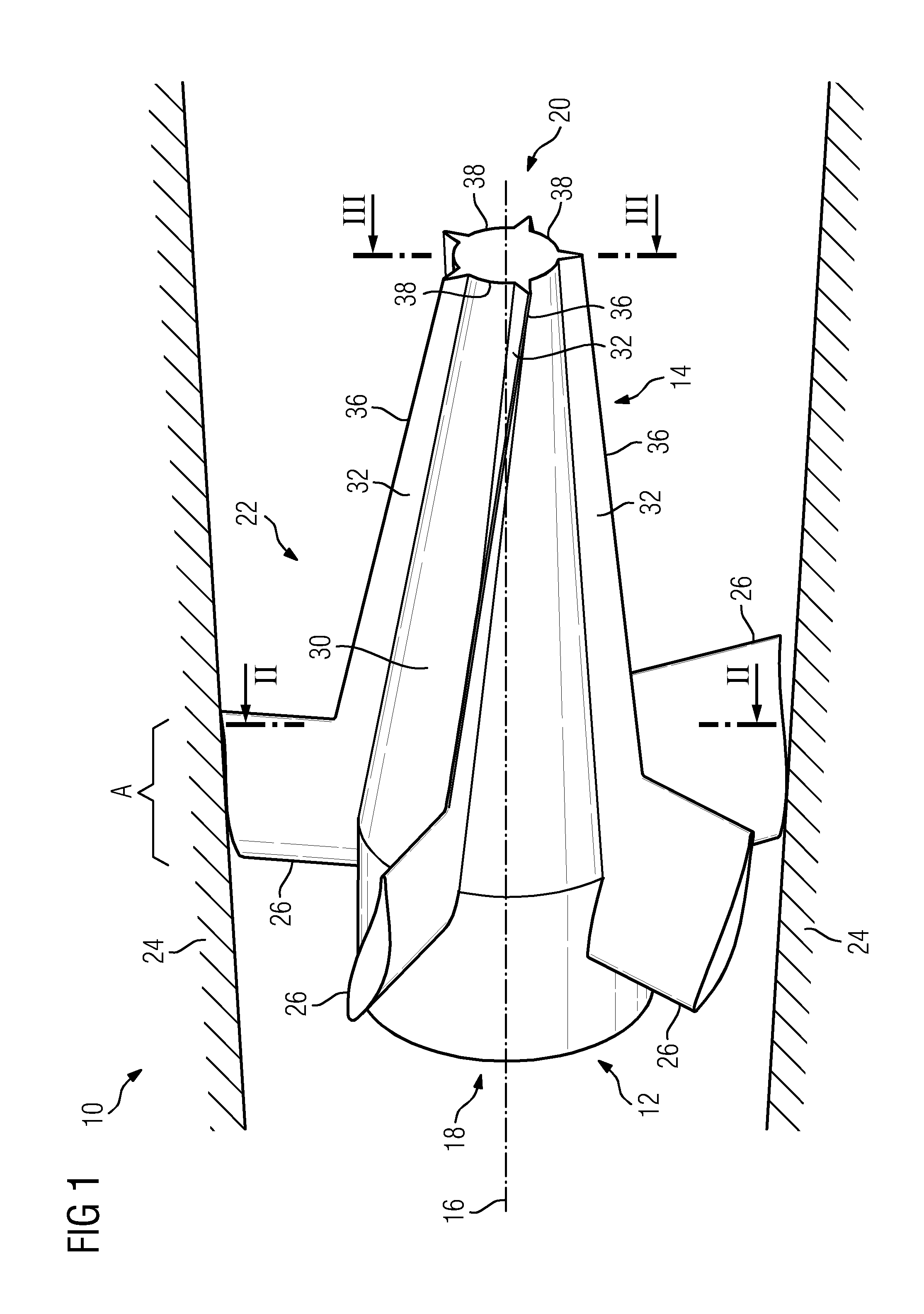
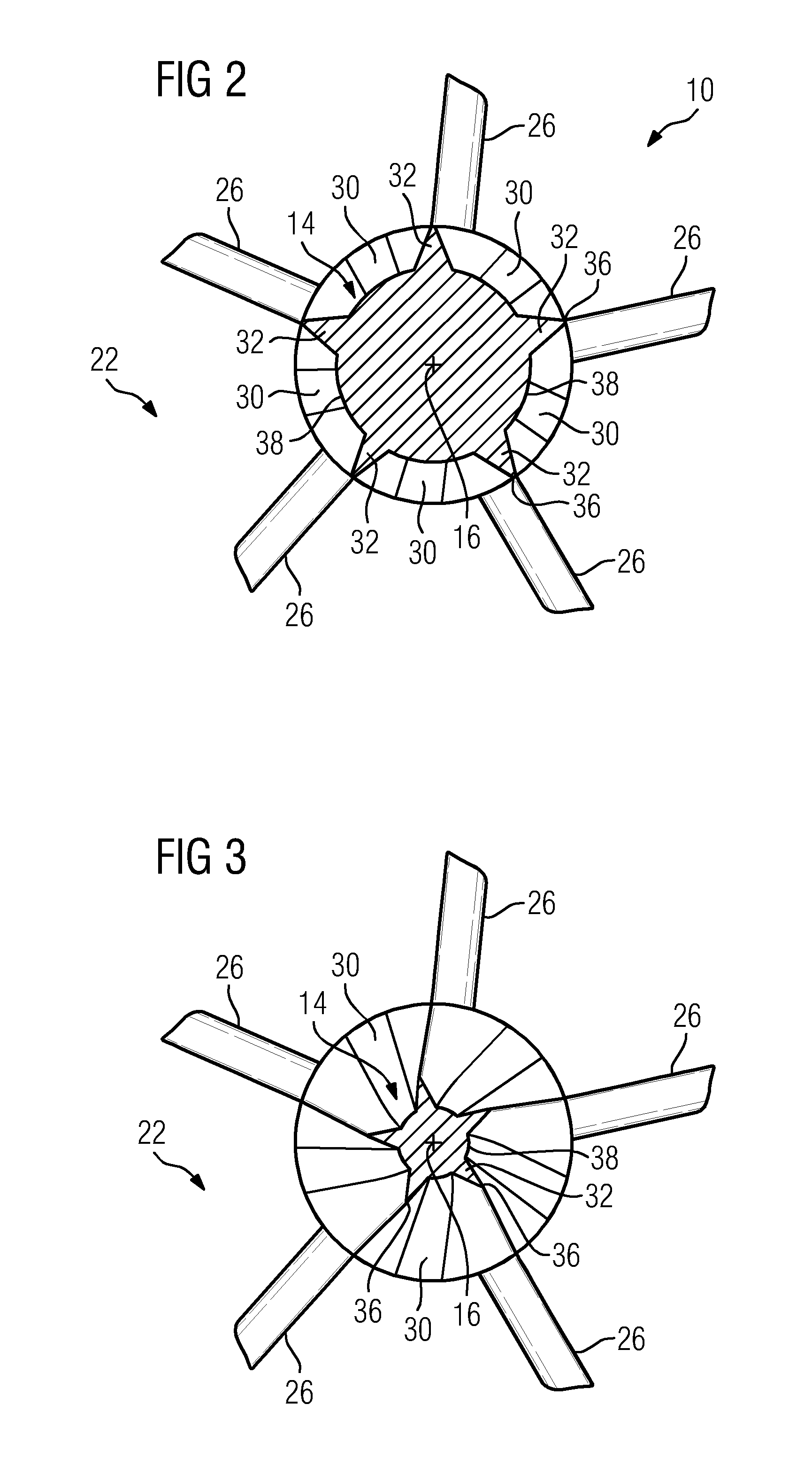
[0017]Shown in FIG. 1 is an exhaust gas diffuser 10 for a gas turbine in a longitudinal section, wherein the bearing star 12, which is arranged in the center of the exhaust gas diffuser 10, for the turbine-side support of the gas turbine rotor and of the guide body 14 which is arranged on the bearing star, is shown in perspective view. The exhaust gas diffuser 10 has a center axis 16 lying in its center, which extends from an inlet-side end 18 to an outlet-side end 20. Provision is made in the exhaust gas diffuser 10 for a flow duct 22, the cross section of which, being perpendicular to the center axis, has an annular contour. The flow duct 22 is delimited in this case by a radially outward disposed outer wall 24. The guide body 14 is arranged in the center of the exhaust gas diffuser 10, that is to say in the region of its center axis 16, and in this case constitutes the radially inward disposed boundary of the flow duct 22. The guide body 14 is supported in this case by five suppo...


PUM


Abstract

An exhaust gas diffuser for a gas turbine includes a flow duct which widens towards a diffuser outlet. The flow duct includes an axially extending guide body, wherein the guide body, at least in an axial section of its longitudinal extent, has a plurality of recesses which are distributed over the circumference and arranged between guide elements. Each guide element extends along a spiral line along the longitudinal extent of the guide body. Further, a gas turbine plant with such an exhaust gas diffuser is provided.

Description

CROSS REFERENCE TO RELATED APPLICATIONS[0001]This application is the US National Stage of International Application No. PCT / EP2011 / 056210 filed Apr. 19, 2011, and claims the benefit thereof. The International Application claims the benefits of European Patent Application No. 10004244.9 EP filed Apr. 21, 2010. All of the applications are incorporated by reference herein in their entirety.FIELD OF INVENTION[0002]The invention relates to an exhaust gas diffuser for a gas turbine, having a flow duct which widens towards the diffuser outlet and in the center of which provision is made for an axially extending guide body.BACKGROUND OF INVENTION[0003]Such an exhaust gas diffuser serves for decelerating the exhaust gas flow of a gas turbine and for recuperating at least some of the dynamic pressure. In order to disclose an exhaust gas diffuser with a comparatively large opening angle of 10° and more, it is known from DE 198 05 115 A1, for example, to provide an axially extending guide body ...

Claims


Application Information

Patent Timeline
IPC IPC(8): F01D25/30
CPCF01D5/145F01D25/30F05D2250/25F05D2250/15F02K1/04
Inventor BROEKER, MARCBUCHAL, TOBIAS
Owner SIEMENS AG
Why Eureka
Try Eureka