
Reduction gearing with a high reduction ratio

a technology of reduction gearing and reduction ratio, which is applied in the direction of toothed gearing, belt/chain/gearing, and detail gearing, etc., can solve the problems of more installation space, high reduction of gearing, and more installation space in the axial direction, so as to achieve simple and inexpensive manufacturing, large reduction, and high degree of efficiency

Inactive Publication Date: 2014-05-29
MAXON MOTOR AG
View PDF6 Cites 5 Cited by
  • Summary
  • Abstract
  • Description
  • Claims
  • Application Information

AI Technical Summary

Benefits of technology

The present invention provides a reduction gearing with a single-stage design that allows for very large reductions with high efficiency. The reduction gearing is simple and inexpensively manufactured, and offers the advantage of being designed in a compact manner. Different embodiments of the reduction gearing are described, including the use of a guide member and the design of a cam contour. The invention is particularly advantaged by the ability to achieve high levels of efficiency with very large reductions.

Problems solved by technology

If the planetary gearing is embodied in a multi-stage manner, however, more installation space is required in the axial direction.
Some applications, however, require highly reduced gearings which may in the radial direction require somewhat more installation space, but must in the axial direction be extremely short.
However, the elastic transmission sleeve requires the use of special wear-resistant materials, which makes the production of such gearings relatively expensive.
In addition, the permanent deformation of the elastic transmission sleeve leads to lossy transmission.
Due to the wobbling motion of the cam disk, however, vibrations can sometimes occur that can have a particularly negative impact on the degree of efficiency of the gearing.
Cycloidal drives are also relatively expensive to manufacture.
All of the aforementioned types of gearings have the disadvantage that no optimum degree of efficiency can be achieved, in particular with very high reduction ratios.
In addition, the aforementioned reduction gearings are also relatively expensive to manufacture.
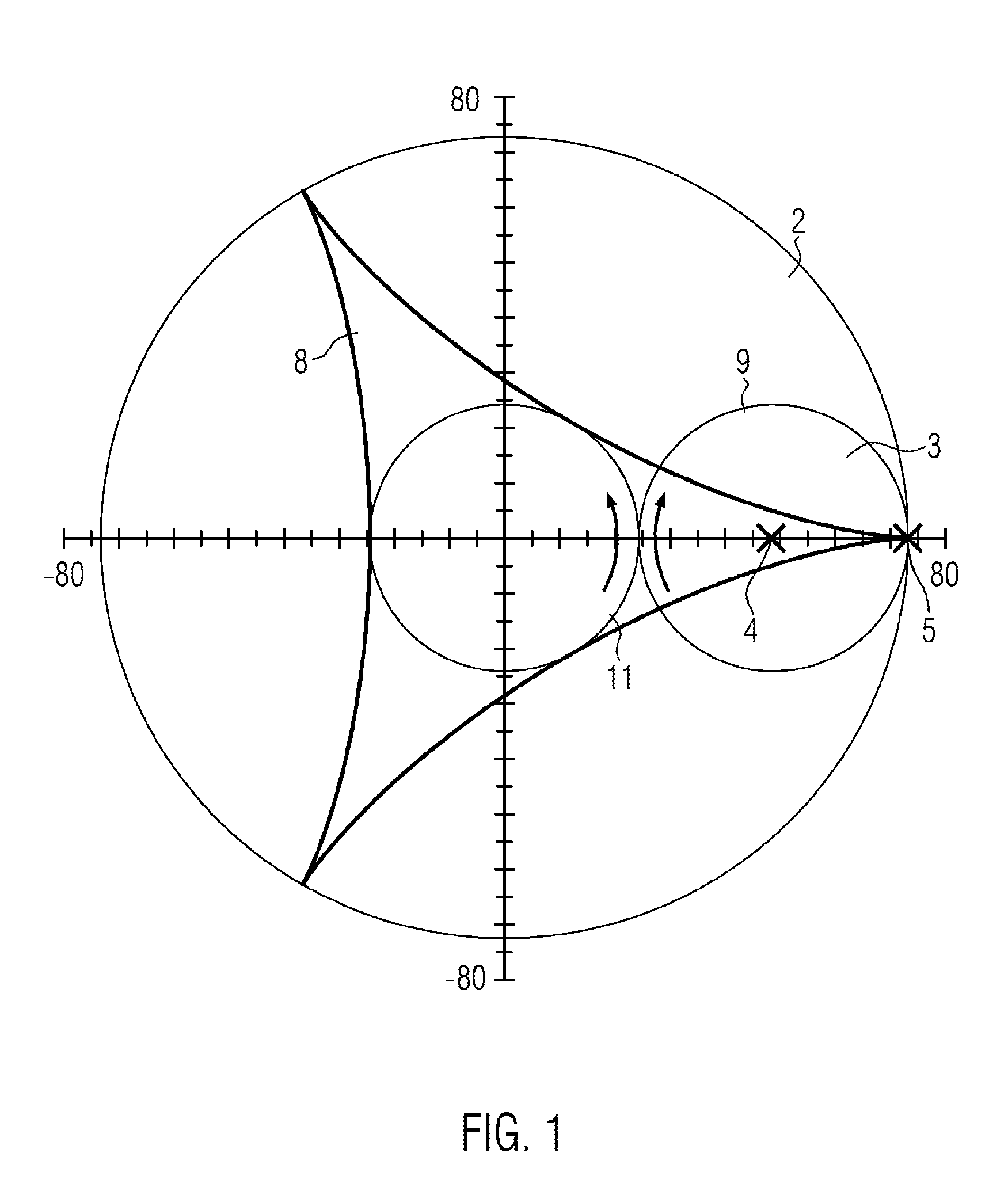
However, it is pointed out that the cam contour of the cam disk can never be an exact hypocycloid due to the necessary finite extension of the guide member.

Method used


Image

  • Reduction gearing with a high reduction ratio
  • Reduction gearing with a high reduction ratio
  • Reduction gearing with a high reduction ratio

Examples


Embodiment Construction

[0032]It applies to the following embodiments that like parts are designated by like reference numerals. If a drawing contains reference numerals which are not explained in the accompanying figure description, then reference is made to preceding or subsequent figure descriptions.

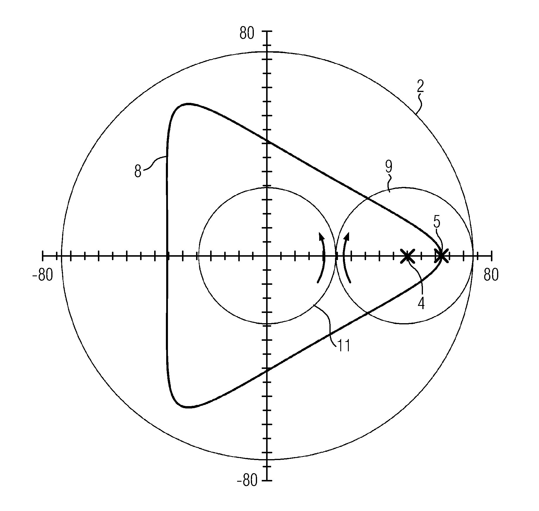
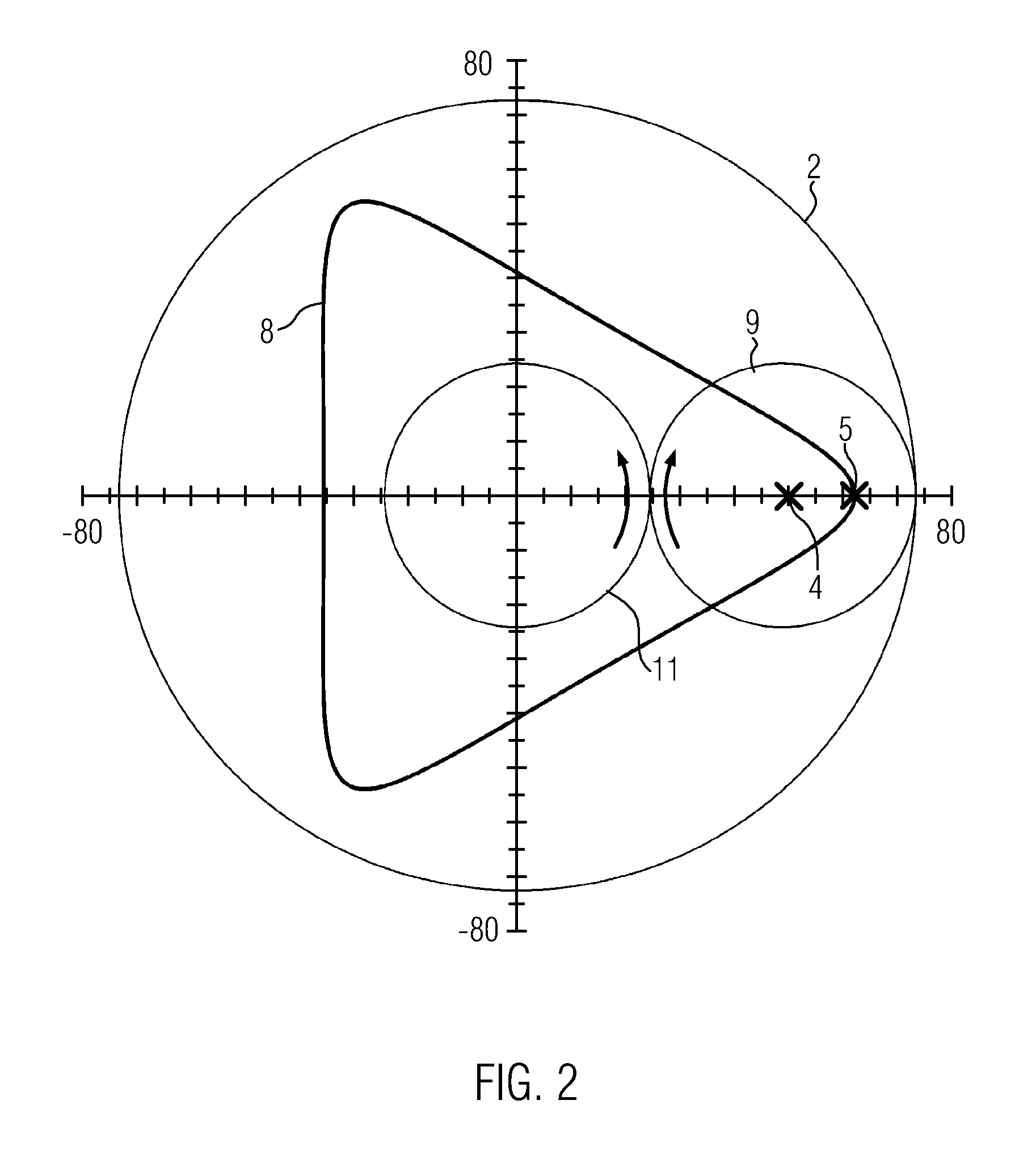
[0033]FIG. 1 shows an arrangement comprising a ring gear 2, a sun gear 11 and a planet gear 3. The ring gear 2 forms the fixed system, the sun gear 11 is arranged concentrically to the ring gear 2 and rotatably mounted relative to the ring gear. The common axis is located at the origin of the coordinate system shown. The planet gear 3 meshes both with the sun gear as well as with the ring gear. Commonly, all three gears comprise gear teeth which are not shown in the drawing. The pitch circle 9 of the planet gear 3 touches the pitch circle of the ring gear and the pitch circle of the sun gear. The axis of the planet gear 3 is denoted by reference numeral 4. When the sun gear 11 is driven, the planet gear 3 ro...


PUM


Abstract

The present invention relates to a reduction gearing with a ring gear, at least one planet gear rolling around in the ring gear and having a planet gear axis, and an output being rotatably mounted coaxially to the ring gear. According to the invention, it is provided that the planet gear comprises a guide member that is spaced apart from the planet gear axis and describes a hypocycloid relative to the ring gear when the planet gear rolls around, wherein guidance is provided between the guide member and a cam disk of the output, such that the output experiences a drive motion by the planet gear rolling around.

Description

[0001]This application claims benefit of the filing date of EP12007974.4, filed Nov. 27, 2012, the entire contents of which is incorporated herein by reference for all purposes.BACKGROUND[0002]1. Field[0003]The present invention relates to a reduction gearing with a high reduction ratio according to the preamble of independent claim 1. Such a gearing comprises a ring gear, at least one planet gear rolling around in the ring gear having a planet gear axis, and an output being rotatably mounted coaxially to the ring gear.[0004]2. Description of Related Art[0005]A reduction gearing of the type mentioned is the well-known planetary gearing. A planetary gearing generally comprises a plurality of planet gears that mesh with both the outer ring gear as well as with an inner sun gear of the planetary gearing. The planet gears are generally rotatably mounted in a planet carrier. The planet carrier itself is aligned coaxially to the ring gear and the sun gear and likewise rotatably mounted. A...

Claims


Application Information

Patent Timeline
IPC IPC(8): F16H1/28
CPCF16H1/28F16H35/02F16H57/08F16H1/32F16H1/2836F16H57/082
Inventor GIEB, KARL-HEINZLUKIC, DARKO
Owner MAXON MOTOR AG
Learn More