Linear generator with a swinging piston

a technology of swinging pistons and linear generators, applied in the direction of dynamo-electric machines, engines without rotary main shafts, electrical apparatus, etc., can solve the problems of low working frequency, inability to fully achieve, bearings are increasingly loaded through even the slightest wear, etc., to achieve quiet operation over long periods, simple space-saving design, and maintenance-free

Inactive Publication Date: 2007-11-06
BUTTON ENERGY ENERGIESYST +1
View PDF21 Cites 5 Cited by
  • Summary
  • Abstract
  • Description
  • Claims
  • Application Information

AI Technical Summary

Benefits of technology

[0005]The technical problem to be solved by the present invention therefore consists in designing an electromagnetic energy converter of the aforementioned type such that, while avoiding the stated disadvantages, the occurrence of sealing problems are avoided and a simple space-saving design may be arrived at which enables very quiet operation over long, maintenance-free periods.
[0006]The invention brings with it the advantage that the gaseous or vaporous medium is conducted, after its expansion, into the working space surrounded by the stator. This enables the creation of a compact, closed system with a common cooling space which may be used, on the one hand, for cooling the components of the electromechanical converter (field coils, armature coil, etc.) and, on the other hand, for cooling and condensation of the gaseous or vaporous medium. Further advantages consist therein that the piston may be designed short and without special bearings, which enables lasting, maintenance-free running of the piston and no external chambers need to be provided, so that no sealing problems can arise.

Problems solved by technology

Due to the plurality of permanent magnets mounted on the working piston and the inertia caused thereby, large accelerating and braking forces have to be applied, which result in low working frequencies.
Due to manufacturing tolerances, this is not fully achievable, however and the bearings are increasingly loaded through even the slightest wear.
Complex designs increase the proneness to faults, which militates against maintenance-free operation of the working piston over several years.
Although an arrangement of this type offers significant advantages with regard to the accelerating and braking forces to be applied, energy converters of this type have previously not become established on the market.
A main reason for this may be seen in the fact that the piston heads impinged upon by the gaseous or vaporous medium are displaceably mounted in chambers arranged outside the stator, whereby sealing problems arise which militate against operation of the piston free from faults and servicing over several years.
Furthermore, it is not possible with these energy converters without further difficulty to guide the gaseous or vaporous medium round a circuit, to realise a compact and space-saving design, and to solve cooling problems arising during operation.

Method used


Image

  • Linear generator with a swinging piston
  • Linear generator with a swinging piston
  • Linear generator with a swinging piston

Examples


Embodiment Construction

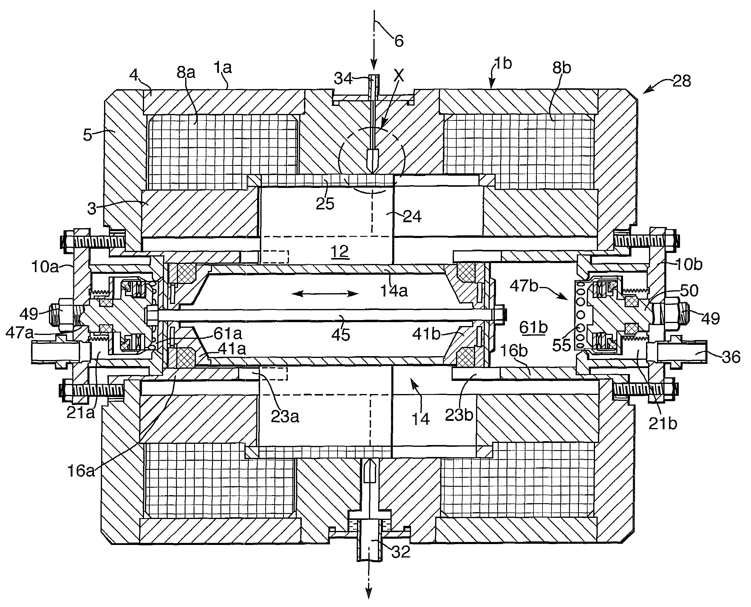
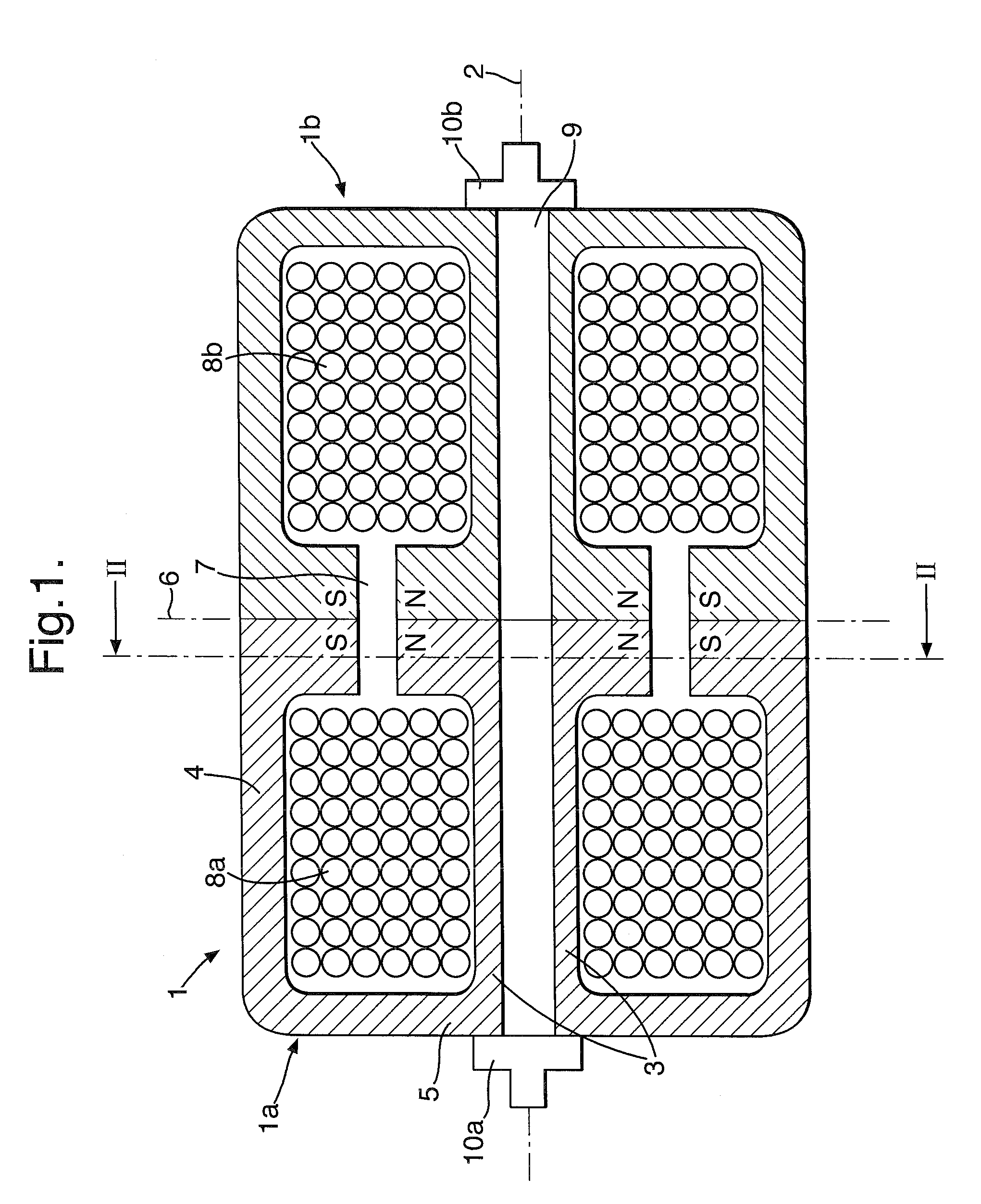
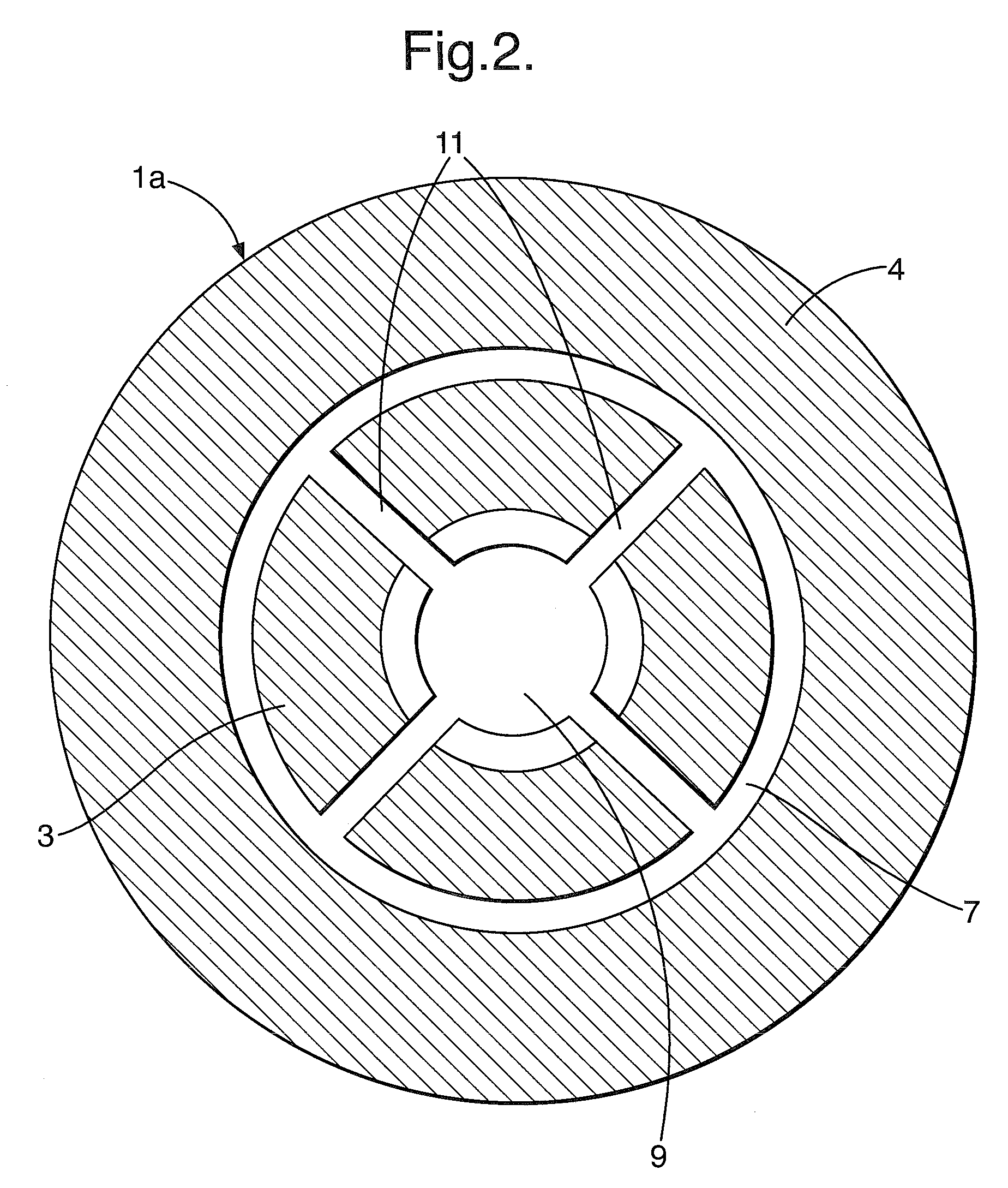
[0019]According to FIGS. 1 and 2, an electromechanical energy converter according to the invention has a stator 1 with two pot-shaped stator members 1a and 1b made of soft iron or similar. The stator member 1a contains a central pole piece 3 coaxial with a longitudinal axis 2 of the converter and an outer pole piece 4 surrounding it coaxially in annular fashion. The central pole piece 3 is preferably formed substantially cylindrical. On the other hand, the outer pole piece 4 is preferably designed as a hollow cylinder and closed by a base 5 at one end. At the open side opposing the base 5 of the pot thus formed, the two pole pieces 3, 4 suitably border a planar end face. Between the pole pieces 3, 4 is a peripheral annular gap. The stator member 1b is suitably formed identical to the stator member 1a and, like it, having rotational symmetry about the longitudinal axis 2.

[0020]As FIGS. 1 and 2 also show, the two stator members 1a, 1b adjoin each other with their end faces lying on th...


PUM


Abstract

An electromechanical energy converter for a gaseous or vaporous medium comprising a stator (1) with two pot-shaped stator members (1a, 1b), each open at one end face and adjoining each other at these end faces, the stator members surrounding a working space (12) and forming a common magnetically permeated air gap (7) in which a coreless armature coil (25) is displaceably arranged. Arranged in the working space (12) is a freely oscillating piston (14) linked to the armature coil (25). Furthermore, at least one source (21a, 21b) for the medium, two reaction chambers (66a, 66b) each assigned to a head (15a, 15b) of the piston (14) and control means (17a, 19a, 22a, 23a; 17b, 19b, 22b, 23b) assigned to the reaction chambers (66a, 66b) for self-control of the piston oscillations are provided, by means of which the reaction chambers (66a, 66b) may be opened to the source (21a, 21b) during the piston oscillations for accepting medium under pressure, and to the working chamber (12) for releasing expanded medium (FIG. 11).

Description

CROSS-REFERENCE[0001]The invention described and claimed hereinbelow is also described in PCT / DE 02 / 04481, filed on Dec. 6, 2002, A 1927 / 2001, filed in Austria on Dec. 7, 2001 and on DE 102 09 858.1, filed in Germany on Mar. 6, 2002. This Austrian Patent Application, whose subject matter is incorporated here by reference, provides the basis for a claim of priority of invention under 35 U.S.C. 119 (a)-(d).BACKGROUND OF THE INVENTION[0002]The invention concerns an electromechanical energy converter designed as a linear generator having a free piston.[0003]In contrast to conventional electromechanical energy converters, linear generators with freely oscillating working pistons dispense with rotary movements and the crank drives needed for these. The energy conversion is provided by the back and forth linear movement of a working piston, often known as a free piston. The conversion of the mechanical energy into electrical energy takes place thereby that the working piston is provided wi...

Claims


Application Information

Patent Timeline
Patent Type & Authority Patents(United States)
IPC IPC(8): H02K33/00F01B11/00F01B23/10H02K7/18H02K35/00H02K35/04
CPCH02K35/00H02K7/1884
Inventor SCHULTE, FRANZ JOSEFKNOPF, RICHARD MATTHIAS
Owner BUTTON ENERGY ENERGIESYST
Why Eureka
Try Eureka