Light diffusing screen

a technology of light diffusion and screen, applied in the field of light diffusion screen, can solve the problems of reducing contrast and whitish image plane, and achieve the effects of reducing scintillation, regulating screen surface roughness, and good picture imag

Inactive Publication Date: 2007-07-12
DAI NIPPON PRINTING CO LTD
View PDF5 Cites 8 Cited by
  • Summary
  • Abstract
  • Description
  • Claims
  • Application Information

AI Technical Summary

Benefits of technology

[0020] The present invention can provide a light diffusing screen that can reduce scintillation of a single light source-type projec

Problems solved by technology

On the other hand, when the surface roughness of the screen is excessively

Method used


Image

  • Light diffusing screen
  • Light diffusing screen
  • Light diffusing screen

Examples


example 1

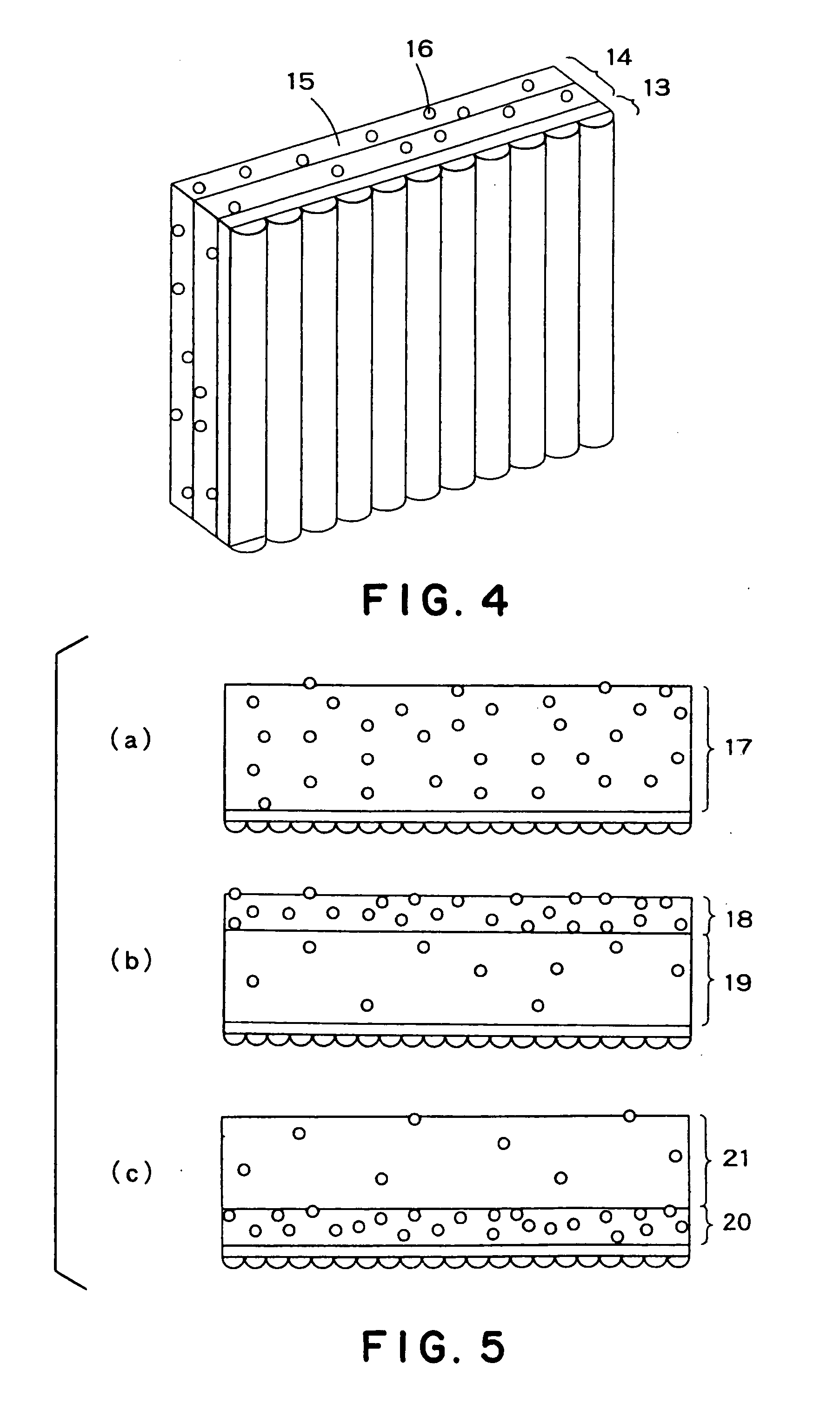
[0044] A light diffusing screen for a single light source-type rear projection television for use in combination with a Fresnel lens sheet was prepared using a lenticular lens layer 13 and a light diffusing layer 14 as shown in FIG. 4. The lenticular lens layer 13 was prepared by forming a lenticular lens formed of a cured product of an ultraviolet curable resin having a lens pitch P=150 μm, a lens transverse diameter a=0.08 mm, and a lens longitudinal diameter b=0.07 mm on 125 μm-thick PET.

[0045] PMMA was used as a light transparent matrix 15 of the light diffusing layer 14, and PMMA and a material prepared by regulating polymerization ratio between PMMA and PS were used as a light diffusing material 16.

[0046] At the outset, the refractive index Np of the light transparent matrix 15 was fixed to 1.49, and the refractive index of the light diffusing material 16 was regulated to 1.52. Using these materials, samples having three light diffusing layer constructions as shown in FIG. 5...

examples 2 to 6

[0050] A light diffusing screen, for a single light source-type rear projection television, for use in combination with a Fresnel lens sheet was prepared using a lenticular lens layer 22 and a light diffusing layer 23 having a double layer structure as shown in FIG. 6.

[0051] The lenticular lens layer 22 was prepared by forming a lenticular lens formed of a cured product of an ultraviolet curable resin and having a lens pitch P=150 μm, a lens transverse diameter a=0.08 mm, and a lens longitudinal diameter b=0.07 mm on 125 μm-thick PET.

[0052] PMMA was used as a light transparent matrix 24 of the light diffusing layer 23, and PMMA and a material prepared by regulating polymerization ratio between PMMA and PS were used as a light diffusing material 25. The refractive index Np of the light transparent-matrix was fixed to 1.49, and the refractive index of the light diffusing material was regulated to 1.52.

[0053] The light diffusing layer had a double layer structure comprising a surfac...

examples 7 to 12

[0056] A light diffusing screen, for a single light source-type rear projection television, for use in combination with a Fresnel lens sheet was prepared using a lenticular lens layer 22 and a light diffusing layer 23 having a double layer structure as shown in FIG. 6. The amount of the diffusing material added to the surface layer side light diffusing layer was regulated so that the surface roughness on the light outgoing face was Ra=0.5 μm.

[0057] The lenticular lens layer 22 was prepared by forming a lenticular lens formed of a cured product of an ultraviolet curable resin and having a lens pitch P=150 μm, a lens transverse diameter a=0.08 mm, and a lens longitudinal diameter b=0.07 mm on 125 μm-thick PET

[0058] PMMA was used as a light transparent matrix 24 of the light diffusing layer, and PMMA and a material prepared by regulating polymerization ratio between PMMA and PS were used as a light diffusing material 25. The refractive index Np of the light transparent matrix was fix...


PUM


Abstract

A light diffusing screen for a single light source-type rear projection television, for use in combination with a Fresnel lens sheet, which can reduce scintillation and, regulate the surface roughness of the screen and provide good images. The light diffusing screen includes: a lens layer which can horizontally refract projected light; and a light diffusing layer provided on a light outgoing side as compared with the lens layer. The light diffusing layer includes a light transparent matrix and light diffusing fine particles formed of a light transparent material dispersed in the light transparent matrix. The light diffusing layer has a multilayer structure of which the outermost layer on the light outgoing side of the light diffusing layer is a layer which diffuses light most strongly, the outermost surface layer on the light outgoing side in the light diffusing screen having a surface roughness Ra of 0.2 μm≦Ra≦1.0 μm.

Description

TECHNICAL FIELD [0001] The present invention relates to a light diffusing screen for use, for example, in transmission projection televisions for single light sources. BACKGROUND ART [0002] CRT light sources have hitherto been mainly used as light sources for rear projection-type projection televisions. In recent years, however, single tube-type light sources such as LCDs or DMDs are becoming mainly used. [0003] In order to reduce external light reflection from the surface of televisions, the formation of a low-reflection layer on the screen surface or the formation of fine concaves and convexes on the screen surface (hereinafter referred to as “mattering”) are favorably carried out. [0004] Further, in the conventional transmission screen, since resin materials are generally used, disadvantageously, the screen surface is likely to be scratched and undergo deposition of dust. [0005] To overcome this problem, it is common practice to adopt the formation of a hardcoat layer on the scre...

Claims


Application Information

Patent Timeline
IPC IPC(8): G03B21/60G03B21/62G03B21/625
CPCG03B21/625G03B21/62G03B21/56G03B21/60
Inventor FUKANO, YOSHIFUMIOSAWA, FUTOSHI
Owner DAI NIPPON PRINTING CO LTD
Why Eureka
Try Eureka