Low-profile articulated electronics enclosure with improved air coolant system

a technology of air coolant and electronics enclosure, which is applied in the direction of casings/cabinets/drawers, cooling/ventilation/heating modifications, instruments, etc., can solve the problems of increased fluctuations, increased environmental contamination risk, and many types of electronics enclosures that are not meant to withstand rigorous or varying environmental conditions

Inactive Publication Date: 2007-07-12
LUCENT TECH INC
View PDF12 Cites 13 Cited by
  • Summary
  • Abstract
  • Description
  • Claims
  • Application Information

AI Technical Summary

Benefits of technology

[0005] An embodiment of the present invention relates to an enclosure system for housing electronic components. The system includes an enclosure having an interior, a base, and a rear sidewall. An air coolant pathway extends from an air intake in the base (near the bottom of the enclosure), through the interior, and out an air exhaust in the rear sidewall. In another embodiment, baffles are disposed in the air intake and exhaust for limiting the entry of contaminants.
[0007] In another embodiment, the enclosure has a number of air exhausts in the rear sidewall, each having a louver for allowing air to escape while minimizing the possible entry of environmental contaminants.
[0009] In another embodiment, the enclosure includes a door for accessing the enclosure interior. Additionally, a support chassis is pivotally connected to the enclosure. The chassis is used to hold or support electronic components. In other words, various electronic devices, modules, or other components may be attached to the chassis. The chassis is laterally pivotally moveable between retracted and deployed positions. In the retracted position, the chassis lies within the enclosure interior; here, the door may be shut to secure the chassis and seal off the interior. In the deployed position (with the door open), the chassis lies rotated out of the enclosure interior. In this position, a user may more easily access electronic components supported by the chassis, allowing for the enclosure to have a shallower depth for placement in locations with limited space. The chassis has a pivot axis on the same side as the door for cooperative movement with the door.

Problems solved by technology

Many types of enclosures for electronics are not meant to withstand rigorous or varying environmental conditions.
However, certain electronic components have to be placed in locations with less stringent environmental controls, or possibly in locations where environmental conditions are more likely to vary, or where the risk of contamination is greater.
Also, junction or distribution boxes housing electronic components for controllably distributing telecommunication feeds in a building may have to be installed in a basement, utility room, closet, or similar location, all of which are subject to greater temperature fluctuations and a greater risk of environmental contamination.
Aside from the increased possibility of exposure to environmental contaminants such as dust, debris, and liquids, the placement of enclosures in certain locations may present issues with respect to space limitations and / or thermal management, e.g., cooling.
For example, if a junction / distribution box is deployed in a utility or other closet having cramped quarters, it may be difficult to arrange for adequate cooling of the electronics in the distribution box given the space constraints of the closet and / or of the distribution box itself.

Method used


Image

  • Low-profile articulated electronics enclosure with improved air coolant system
  • Low-profile articulated electronics enclosure with improved air coolant system
  • Low-profile articulated electronics enclosure with improved air coolant system

Examples


Embodiment Construction

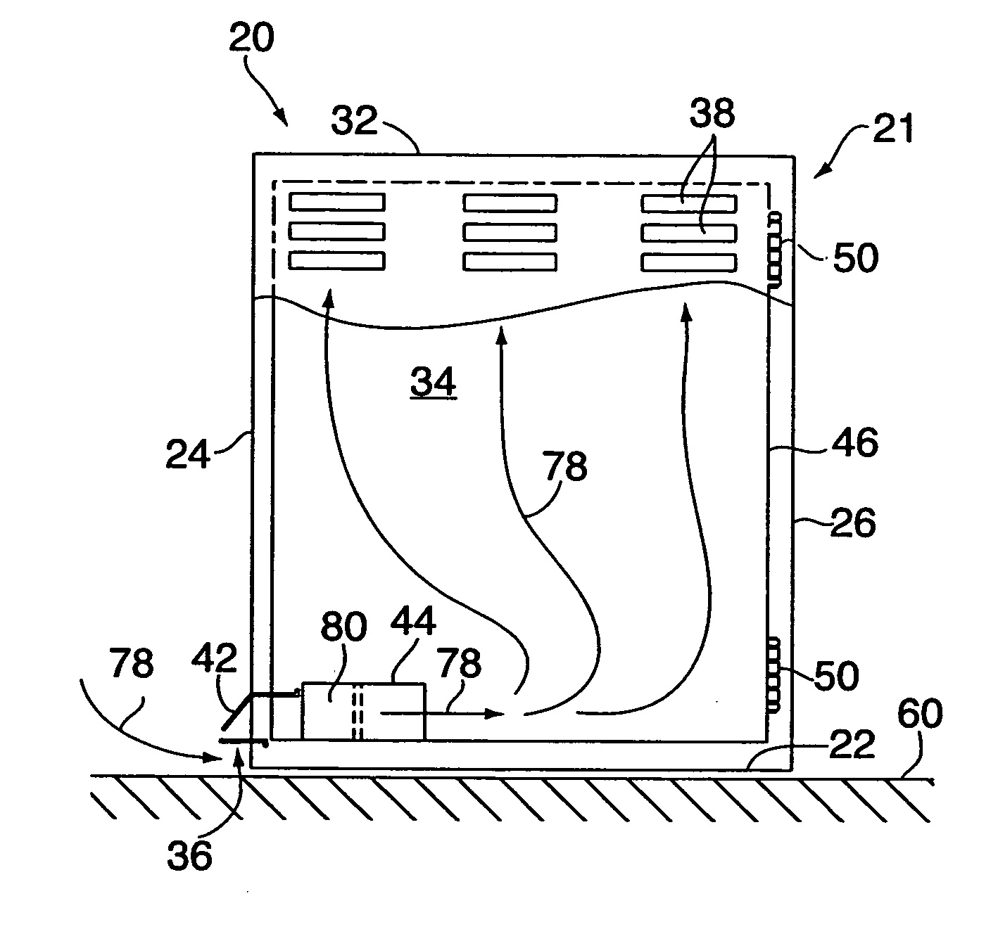
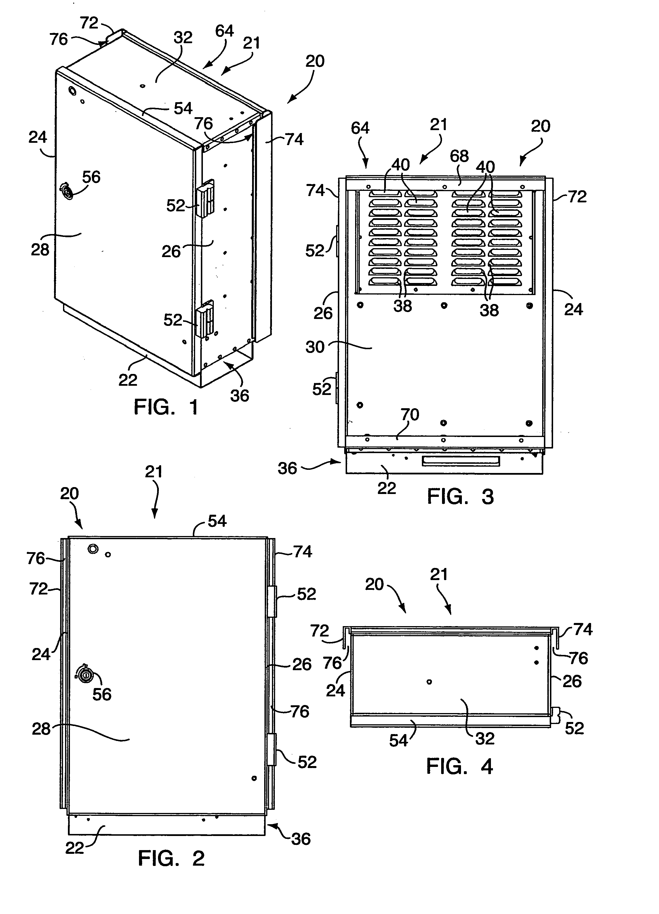
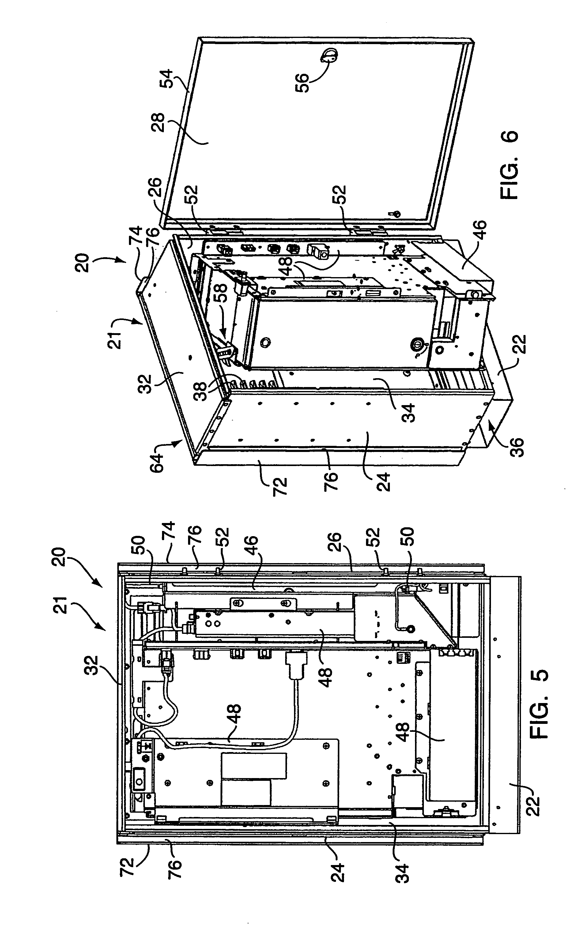
[0025] With reference to FIGS. 1-9B and 10B, an embodiment of the present invention relates to an articulated enclosure system 20 for housing electronic components. The system 20 includes an exterior frame or enclosure 21 having a base 22, left and right sidewalls 24, 26, front and rear sidewalls 28, 30, and a top sidewall 32, all of which define an interior 34 of the enclosure. One or more air intakes 36, e.g., passageways through which air can flow, extend from the base 22 (at the exterior bottom of the enclosure 21) into the enclosure interior 34. The rear sidewall 30 has one or more air exhaust ports 38 extending therethrough. The exhaust ports 38 are each provided with a baffle such as a louver 40 attached to the rear sidewall 30. The air intake 36 is also provided with a baffle 42. The baffles 40, 42 allow air to pass while limiting the ingress of environmental contaminants such as dust, debris, and sprayed liquid. In operation, air is drawn into the enclosure through the air ...


PUM


Abstract

A system for housing electronic components includes an enclosure with an interior, a door for accessing the interior, and a chassis. The components are attached to the chassis, which is pivotally connected to the enclosure for movement between retracted and deployed positions. In the former, the chassis lies within the interior. In the latter, it lies rotated or swung out the front of the enclosure, allowing for the components to be accessed while minimizing the depth / size of the enclosure. The enclosure includes an air intake in the base of the enclosure, and air exhaust ports in the rear of the enclosure, both protected by baffles / louvers. Air is drawn through the intake (using a fan), up through the interior for cooling purposes, and out the rear of the enclosure through the exhaust ports. This pathway has been found to minimize the ingress of sprayed liquid, for compliance with IEC IP44.

Description

FIELD OF THE INVENTION [0001] The present invention relates to cabinets or enclosures and, more particularly, to cabinets or enclosures for holding electronic components in a secure manner. BACKGROUND OF THE INVENTION [0002] Metal or polymer cabinets or other enclosures are frequently used to house disparate or related electronic components at a point of deployment. For example, the components of a computer terminal (e.g., disk drives and processor boards) may be housed in a case having an outer enclosure, an inner support frame or structure for securely holding the components relative to one another, and one or more doors or hatches for a user to access the interior of the enclosure. Such enclosures are provided to protect the components from external contamination (especially where the components may not be provided with much protection of their own), and to secure the components against tampering and unauthorized removal. Enclosures are also used to space components apart from on...

Claims


Application Information

Patent Timeline
Patent Type & Authority Applications(United States)
IPC IPC(8): H05K7/20
CPCH05K7/20145G06F1/16G06F1/181G06F1/20H04B1/036H05K5/0217H05K5/0214
Inventor PONGRACZ, DAVID J.SHEMAN, RODNEY M.
Owner LUCENT TECH INC
Why Eureka
Try Eureka