Card connector

a card connector and connector technology, applied in the direction of connecting devices, instruments, conveying record carriers, etc., can solve the problems of difficult to mount the card connector automatically on the printed circuit board or the like, the complexity of the connector construction, and the inability to retain the connection between the card and the connector firmly, etc., to achieve easy removal, simple structure, and easy to attach and detach the effect of the card

Inactive Publication Date: 2007-07-12
MATSUSHITA ELECTRIC WORKS LTD
View PDF8 Cites 36 Cited by
  • Summary
  • Abstract
  • Description
  • Claims
  • Application Information

AI Technical Summary

Benefits of technology

[0009] According to such a constitution, the card can be contained and held in the recess with the stationary hooking portion and the movable hooking member provided on the body, so that an additional cover or a card holder becomes unnecessary, and thereby, a compact card connector having a simple structure can be obtained. Furthermore, an attaching and detaching operation of a card to the connector can be performed with moving it in a direction connecting the first face and the second face of the body of the movable hooking member, for example, in an anteroposterior direction, so that the attaching and detaching operation of the card becomes easier. Still furthermore, since the tapered face is formed on the movable hooking member, it is possible to move the movable hooking member toward the second face side against the

Problems solved by technology

Thus, it is difficult to mount this connector automatically on the printed circuit board or the like.
However, such a constitution cannot retain the connection between the card and the connector firmly.
Therefore, it is necessary to provide a locking mechanism additionally to retain the connection for the purpose of ensuring the connection between the connector and the

Method used


Image

  • Card connector
  • Card connector
  • Card connector

Examples


first embodiment

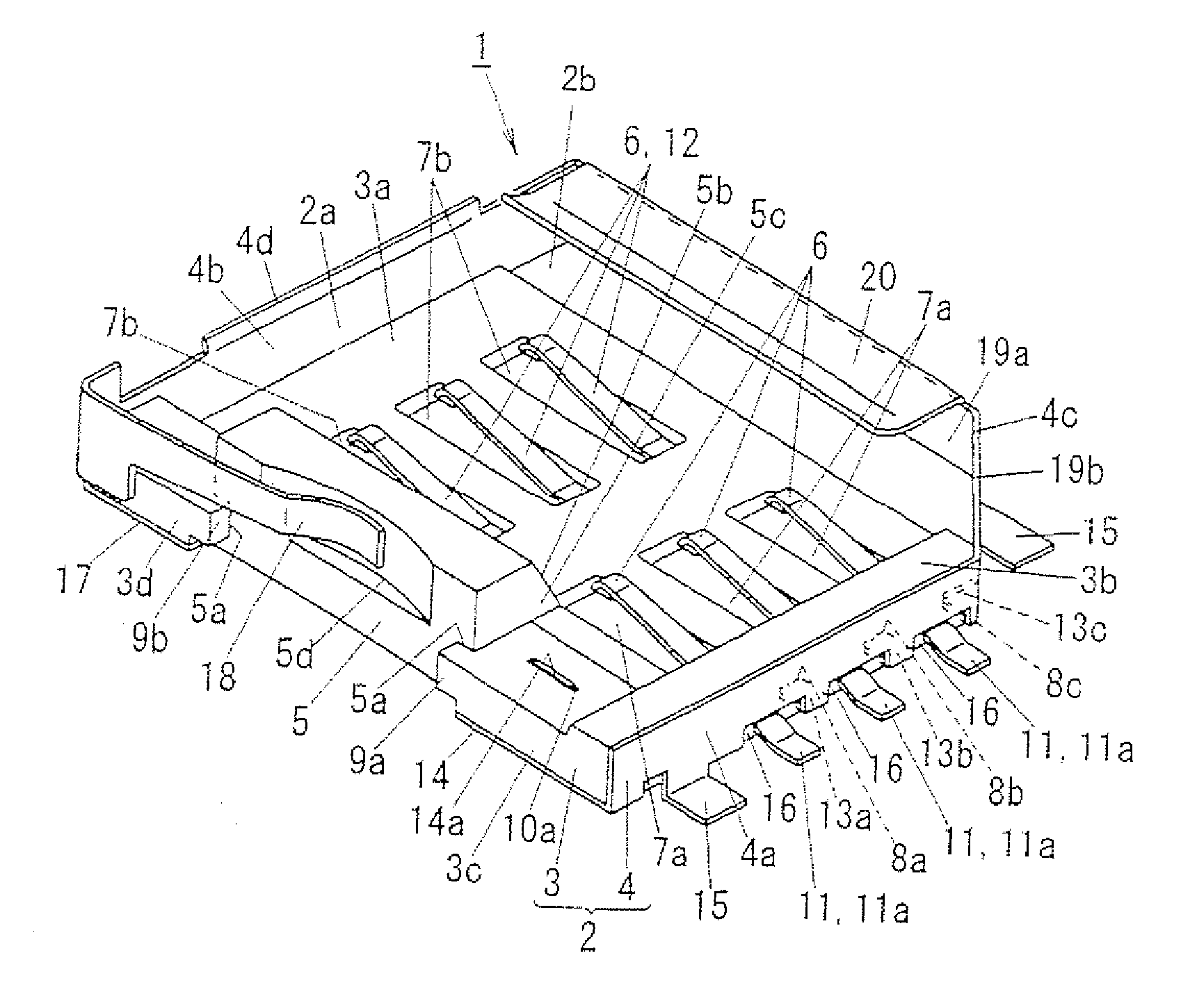
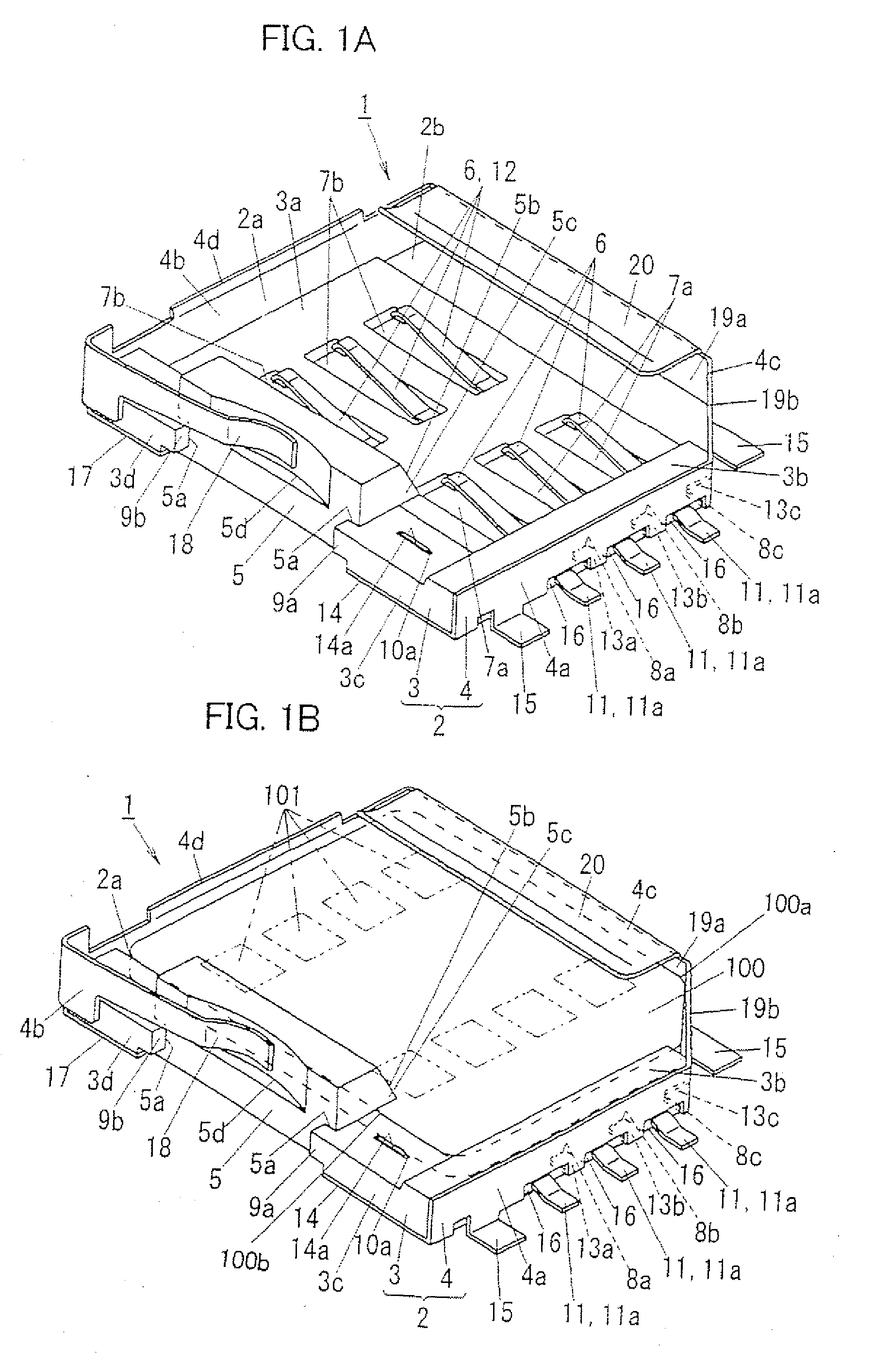
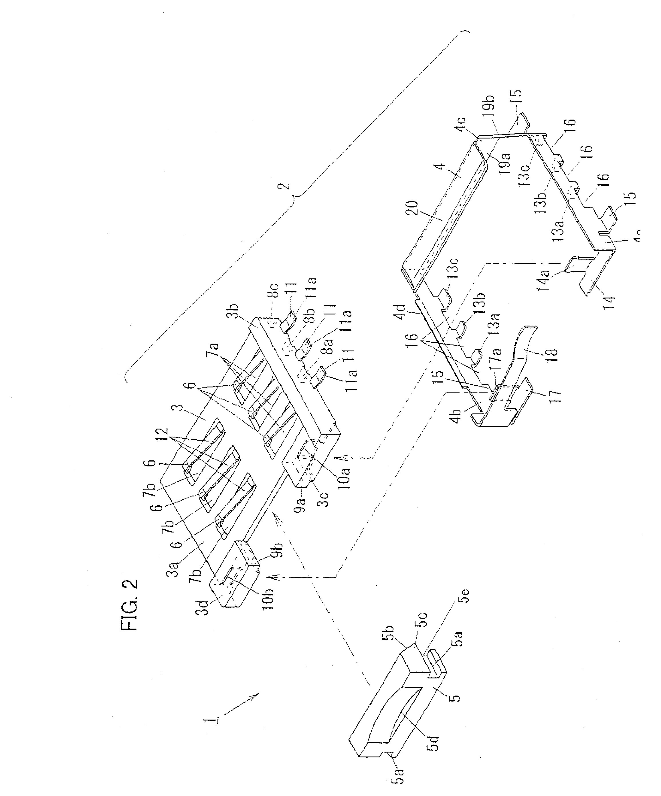
[0021] A card connector (hereinafter, described simply as “the connector”) 1 in accordance with a first embodiment of the present invention is described with reference to drawings. Besides, in each following embodiment, in FIG. 3A, for example, an upward direction is defined as a rear face (a first face) side or a backward of the connector 1, a downward direction is defined as a front face (a second face) side or a front of the connector 1, a leftward direction is defined as a left side of the connector 1, a rightward direction is defined as a right side of the connector 1, and a front side of the surface of the paper sheet is defined as an upward of the connector 1, for ease of description. Furthermore, in FIG. 3A, the upward direction is defined as a front end (a first end portion) of an IC card 100, the downward direction is defined as a rear end (a second end portion) of the IC card 100, the front side of the surface side of the drawing sheet is defined as a front face of the IC...

second embodiment

[0057] Subsequently, a card connector 1 (SIC) in accordance with a second embodiment of the present invention is described. In the first embodiment described above, the connector 1 is composed of only the body 2, and also, the body 2 is composed of only the three components, that is, the base 3, the shell 4, and the movable hooking member 5. However, in the connector 21 of the second embodiment, a number of components is further reduced, so that a body 26 is composed of only two components of a hooking clasp 22 and a base 27. Besides, as for the constitution similar to that of the first embodiment described above, the same symbols are provided, and then, the description of them is omitted.

[0058] As shown in FIG. 7, the hooking clasp 22 comprises a movable hooking member 23 and a pair of plate springs 24 integrally, and it is formed of a metal plate having elasticity. The hooking clasp 22 is bilaterally-symmetric with respect to the center of the movable hooking member 23, and long ...


PUM


Abstract

A compact and simple constitution of a card connector, with which attaching and detaching works of a card can be performed easily, is provided. The connector 1 comprises: a body 2 having a recess 2a for a card 100; six contact springs projecting from a bottom face 3a of the recess 2a on which the IC card 100 is disposed, and elastically contacting with contact terminals 101 of the card 100; a stationary hooking portion 20 provided on a rear face side of the body 2; a movable hooking member 5 provided on a front face side of the body 2, and movable in a anteroposterior direction of the body 2; and a plate spring 18 for charging the movable hooking member 5 toward the rear face of the body 2, and wherein a tapered face 5b is formed on a rear face side of a hooking portion 5c so as to come closer to the rear face of the body 2 as approaching to the bottom face 3a of the recess 2a. A front end of the IC card 100 is held between the stationary hooking member 20 and the bottom face 3a of the recess 2a, and a rear end of the IC card 100 is held by means of the hooking portion 5c provided on the rear face side of the movable hooking member 5 and the bottom face 3a of the recess 2a.

Description

TECHNICAL FIELD [0001] The present invention relates to a card connector to connect a card such as an IC card or the like to an external circuit. BACKGROUND ART [0002] Conventionally, a card connector to connect an IC card which includes an IC chip composed of a memory, a CPU, or the like to an external circuit such as a printed circuit board or the like is provided. [0003] According to Japanese Patent No. 2860362, a card connector, which comprises a body contiguously supporting an IC card and a cover rotatably attached to the body, is proposed. [0004] As for this card connector, since the cover is rotatably attached to the body, the cover should be handled together with the body for mounting this connector on a printed circuit board or the like. Thus, it is difficult to mount this connector automatically on the printed circuit board or the like. Furthermore, as for this connector, the connection of the card and the connector is retained with directly contacting an end face of the c...

Claims


Application Information

Patent Timeline
IPC IPC(8): H01R13/62
CPCG06K7/0021H01R13/2442G06K13/085H01R13/639G06K17/00H01R12/71
Inventor TANAKA, HIROHISAYAMAMOTO, TOSHIHIROIIDA, MITSURUINABA, YOSHIHISA
Owner MATSUSHITA ELECTRIC WORKS LTD
Why Eureka
Try Eureka