Resorbable anterior cervical plating system with screw retention mechanism

a technology of fixing mechanism and anterior cervical plate, which is applied in the field of bone stabilization or fixation assembly, can solve the problems of insufficient mechanical strength or holding force, dislodge or backout of fasteners, and device remains in the body or is surgically removed, so as to maintain compressive load on the graft and promote fusion

Inactive Publication Date: 2007-07-12
SYNTHES USA
View PDF28 Cites 85 Cited by
  • Summary
  • Abstract
  • Description
  • Claims
  • Application Information

AI Technical Summary

Benefits of technology

[0015] The bone fixation assembly may have applications in the spine in the cervical and lumbar regions, including for example anterior cervical plating, and employ a retention mechanism. This retention mechanism has at least

Problems solved by technology

However, the metallic devices have their disadvantages, such that when the bone defect is repaired the device either remains in the body or is surgically removed.
A disadvantage of these non-metallic devices is that

Method used


Image

  • Resorbable anterior cervical plating system with screw retention mechanism
  • Resorbable anterior cervical plating system with screw retention mechanism
  • Resorbable anterior cervical plating system with screw retention mechanism

Examples


Embodiment Construction

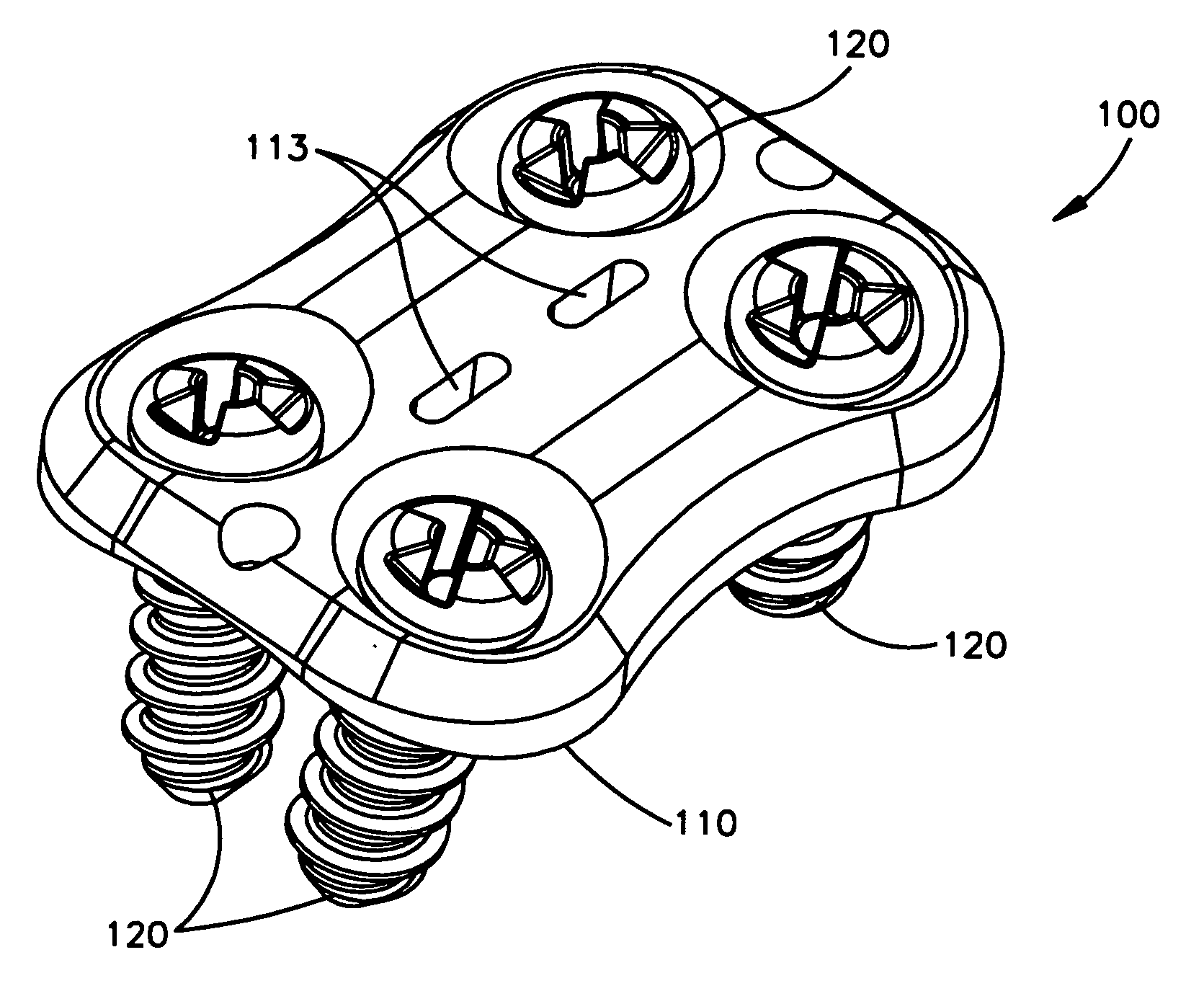
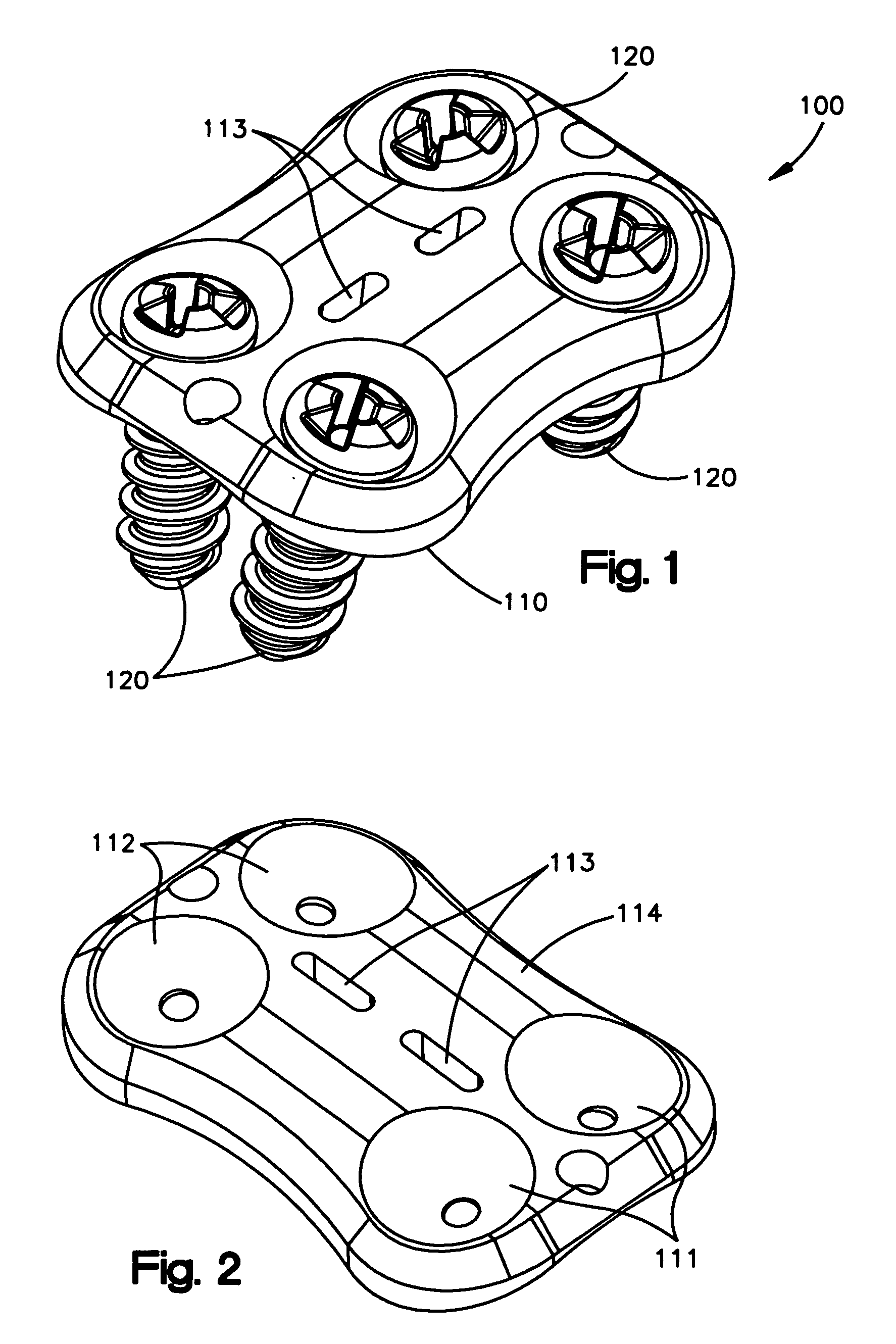
[0038] A preferred embodiment of a bone plate assembly 100 (also referred to as a bone fixation assembly or bone stabilization assembly) is depicted in FIG. 1, and includes a bone plate 110 and fasteners 120. The bone plate assembly is preferably for use in the human spine, preferably in the cervical and / or lumbar regions. The bone plate assembly may be attached, for example, to two or more adjoining vertebrae and functions to prevent graft extrusion / expulsion. With proper strength of the bone plate, the bone plate assembly may also provide stability for alignment and maintaining adjacent vertebrae in a predetermined spatial relationship to each other. The bone plate assembly may be used for other regions other than the spine, such as for example, long bones.

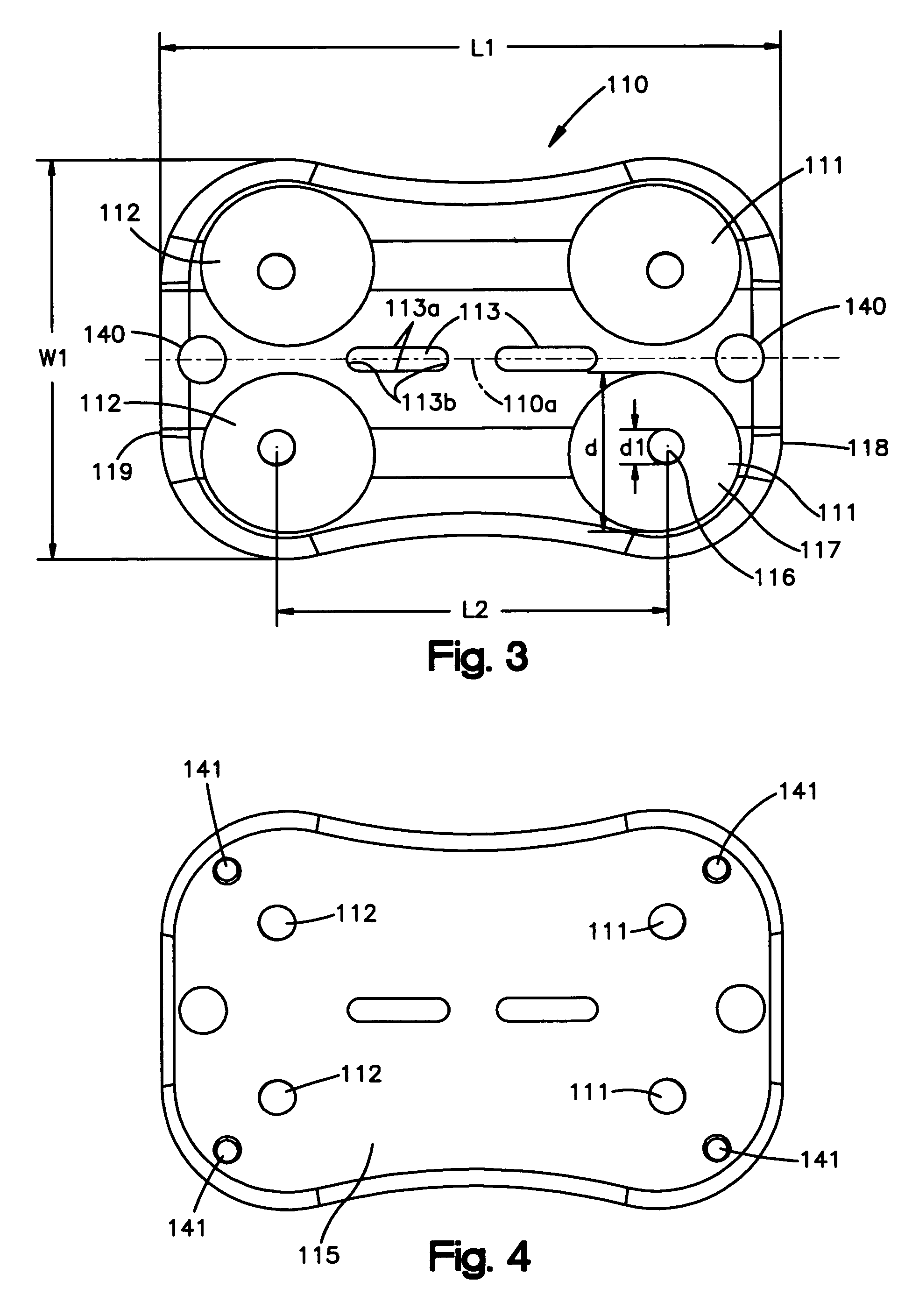
[0039] Bone plate 10 (FIGS. 2-6) includes an upper side 114 (FIG. 3) and an underside or lower side 115 (FIG. 4) with fixation holes extending from the upper side 114 to the underside 115. The underside 115 may be curved transv...


PUM


Abstract

A bone stabilization or fixation assembly may include a bone plate having an upper side and an underside and at least one fixation hole having a first diameter and the hole extending from the upper side to the underside. The area of the bone plate adjacent the fixation hole has a first thickness. The bone stabilization assembly further includes at least one fastener having a head, a shaft, and a relief. The head has a larger dimension than the shaft. The shaft may have threads having a pitch, a core diameter and an outer thread diameter. The relief has a length and a second diameter. The first diameter of the fixation hole may be smaller than the outer thread diameter but larger than the second diameter of the relief. Also, the length of the relief may be greater than the first thickness of the bone plate. The first diameter may be greater than, equal to, or less than the core diameter of the shaft.

Description

[0001] The present application claims priority to U.S. Provisional Application No. 60 / 753,372 filed on Dec. 21, 2005, the entire contents of which is expressly incorporated herein by reference.TECHNICAL FIELD [0002] The present invention is directed to a bone stabilization or fixation assembly, particularly for use in the spine. BACKGROUND OF THE INVENTION [0003] Orthopedic fixation devices are frequently coupled to bone by the use of fasteners, such as screws or pins. For example, bone plates can be secured to bone with screws inserted through plate holes. In the past, many of the orthopedic devices were made primarily from metallic materials. The metallic devices have some advantages, such as the ability to sterilize and having the necessary strength for support and fixation. However, the metallic devices have their disadvantages, such that when the bone defect is repaired the device either remains in the body or is surgically removed. [0004] More recently, improved materials, inc...

Claims


Application Information

Patent Timeline
IPC IPC(8): A61F2/30
CPCA61B17/7059A61B17/8047A61B17/8052A61B2017/00915A61B19/54A61B2017/00004A61B17/866A61B90/39A61B17/70A61B17/80A61B17/86
Inventor BURNS, PAULKOCH, DAVIDROTH, CHRISTOPH A.
Owner SYNTHES USA
Why Eureka
Try Eureka