
Method and apparatus for automated simulation and design of corneal refractive procedures

a corneal refractive and automated simulation technology, applied in the field of corneal refractive procedures, can solve the problems of not accurately modeling any real strain relationship felt by the cornea, unable to disclose any particular adequate mathematical model of corneal strain relationship or any specific recommendation of surgical design that has been validated, etc., to reduce the invasiveness of surgical procedures, reduce the multi-focal imaging of the central cornea, and reduce the effect of irregular astigmatism

Inactive Publication Date: 2007-07-12
HALL GARY W
View PDF3 Cites 6 Cited by
  • Summary
  • Abstract
  • Description
  • Claims
  • Application Information

AI Technical Summary

Benefits of technology

[0010] It is another object of the invention to provide a system and method that result in improved predictability of outcomes of corneal surgery.
[0016] It is another object of the invention to reduce the likelihood of postoperative complications in the eye including, but not limited to over-correction or under-correction of pre-existing refractive errors.

Problems solved by technology

All such refractive procedures are characterized by difficulty in predicting both the immediate and long term results, because of errors in calculations of pre-surgical measurements, failure to precisely implement the planned surgical techniques, and biological variances which affect immediate and long term results.
These models, by implicitly assuming uniform strain relationships in the cornea, do not accurately model any real strain relationships felt by the cornea.
However, the article fails to disclose any particular adequate mathematical model of the corneal strain relationships or any specific recommendation of surgical design that has been validated with clinical data.
These procedures do not account for the actual strain relationships in the cornea and frequently result in large amounts of under-correction or over-correction.

Method used


Image

  • Method and apparatus for automated simulation and design of corneal refractive procedures
  • Method and apparatus for automated simulation and design of corneal refractive procedures
  • Method and apparatus for automated simulation and design of corneal refractive procedures

Examples


Embodiment Construction

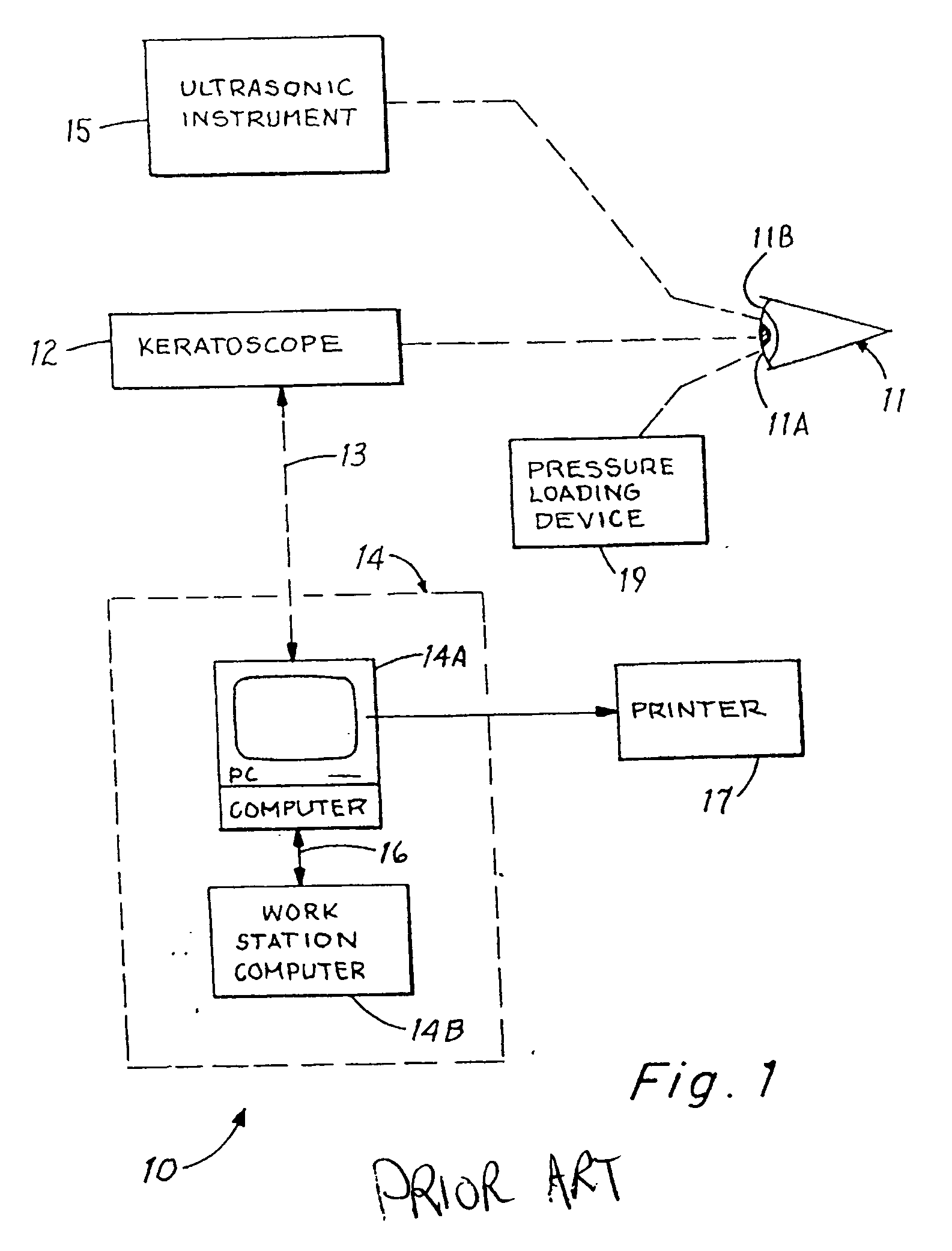
[0032] The present invention involves constructing a strain determining model of a human eye using a suitable three-dimensional finite element analysis (FEA) model that includes a mesh that generally corresponds to the shape of the human eye. The finite element mesh is obtained using back calculated strain data and translated into the nodal points of the FEA model and describes the strain characteristics of the human eye. The nodal points in a small region are connected to each other, to form a finite set of elements. The elements are connected to each other by means of sharing common nodes. The strain values at any particular region are obtained by back calculation and are applied to the elements. The “loading” of the finite element mesh structure is represented by the intraocular pressure, and the resistance of the structure to such applied “loading” is measured by the stiffness of the structure, which is computed on the basis of its geometry, boundary conditions, and its material...


PUM


Abstract

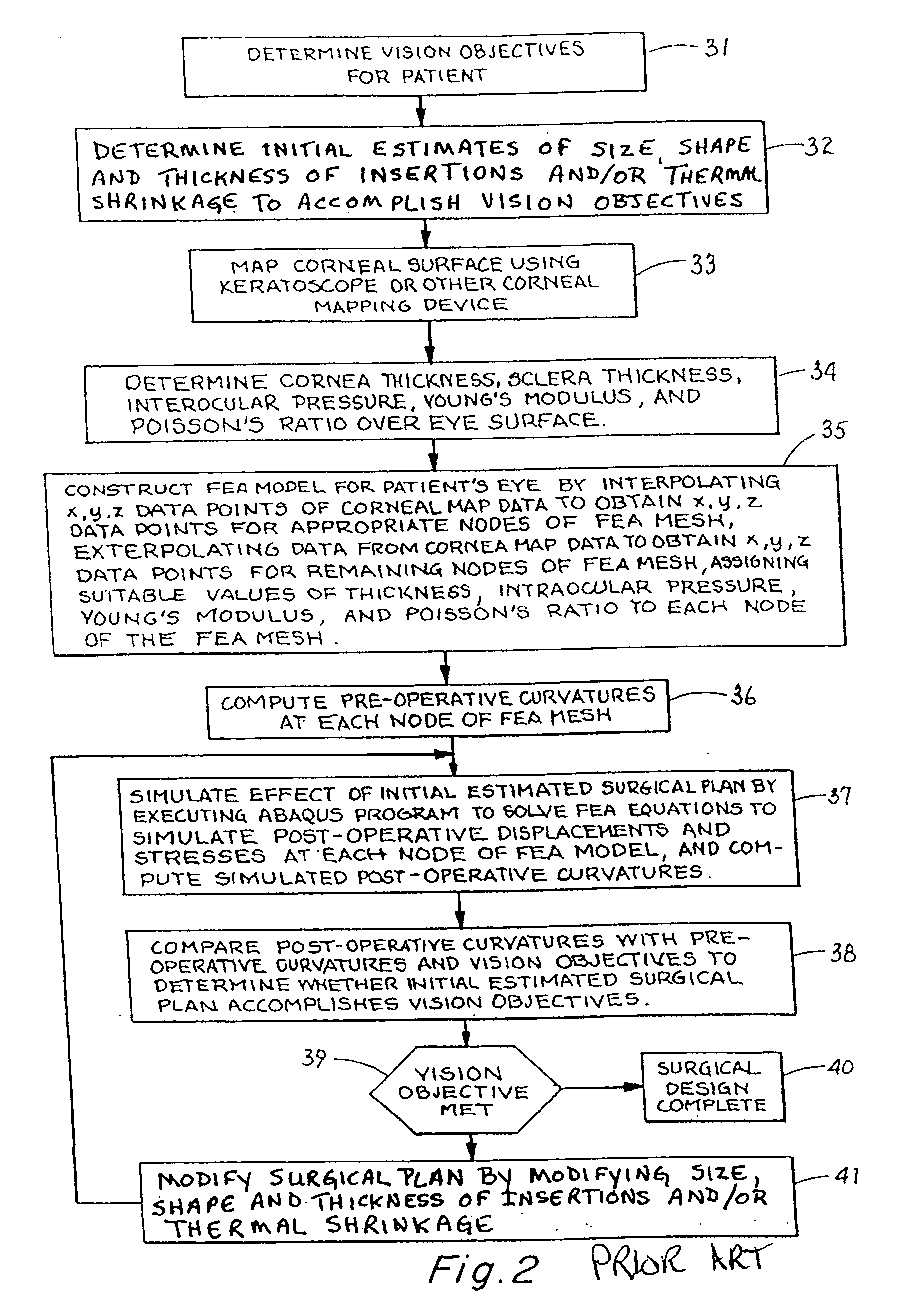
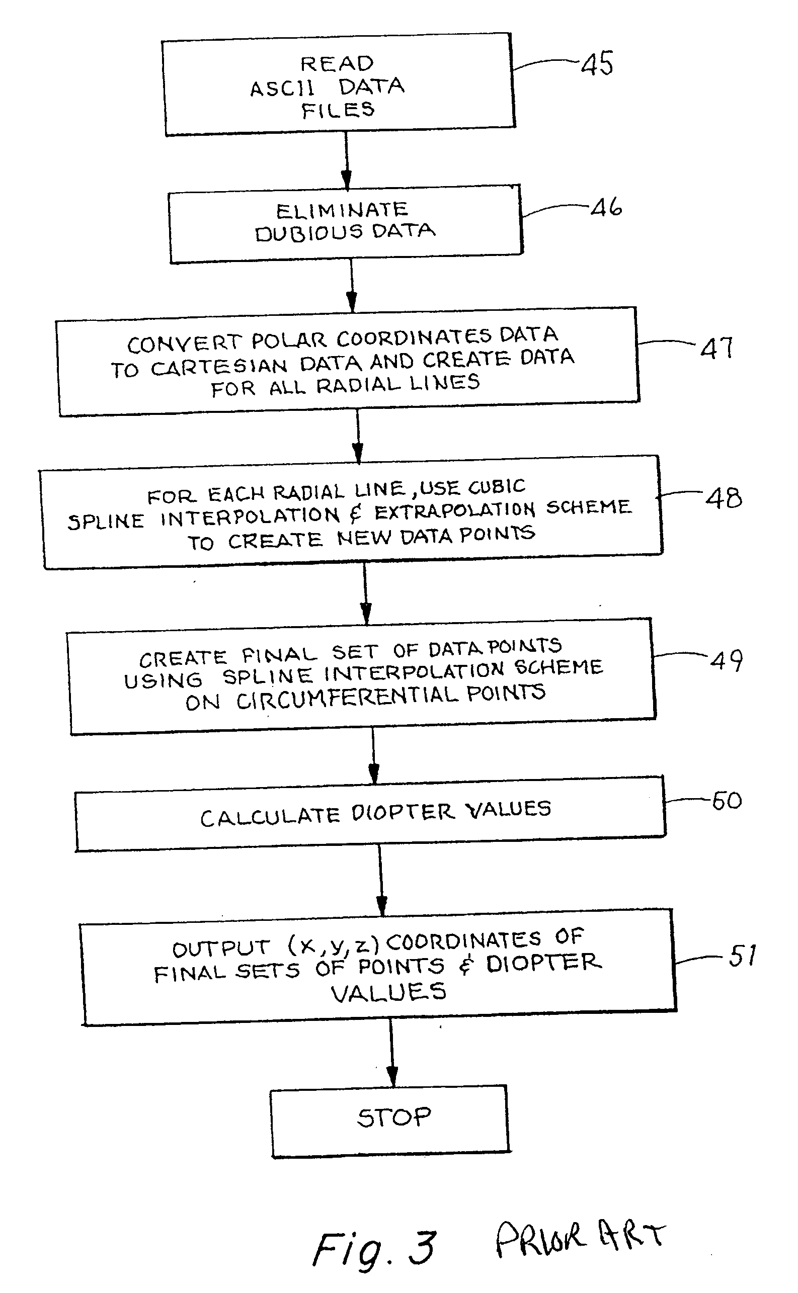
A technique for automated design of a corneal surgical procedure includes topographical measurements of a patient's eye to obtain corneal surface topography. Conventional techniques are used to obtain the thickness of the cornea and the intraocular pressure. The topographical information is interpolated and extrapolated to fit the nodes of a finite element analysis model of the eye, which is then analyzed to predict the initial state of strain of the eye and obtain pre-operative curvatures of the cornea. Insertion and thermal shrinkage data constituting the “initial” surgical plan is incorporated into the finite element analysis model. A new analysis then is performed to simulate resulting deformations, stresses, strains, and curvatures of the eye. They are compared to the original values thereof and to the vision objective. If necessary, the surgical plan is modified, and the resulting new insertion or thermal shrinkage date is entered into the model and the analysis is repeated. This procedure is repeated until the vision objectives are met.

Description

FIELD OF THE INVENTION [0001] The present invention relates to systems and techniques for mathematically modeling a human eye using calculated strain values for a human eye and using a mathematical model to simulate strain deformation of the eye by hypothetical incisions, excisions, ablations, or prosthetic insertions to arrive at an optimum surgical design by identifying the number, shape, location, length, and depth of the incisions, excisions, ablations, or of corneal prosthetic insertions required to obtain a uniform or near homogeneous strain pattern on the cornea. BACKGROUND [0002] The present invention relates to systems and techniques for mathematically modeling a human eye using calculated strain values obtained from data measured from a human eye. The mathematical model of the present invention simulates the change in strain conditions of the cornea effected by a set of hypothetical incisions, excisions, ablations, or corneal prosthetic insertions. A near uniform strain pa...

Claims


Application Information

Patent Timeline
Patent Type & Authority Applications(United States)
IPC IPC(8): G06G7/48A61B3/107A61B3/16A61B8/10A61F9/01
CPCA61B3/0025A61B3/107A61B3/165A61B8/10A61F2009/00895A61F9/00821A61F2009/00853A61F2009/00872A61F9/00802
Inventor HALL, GARY W.
Owner HALL GARY W
Learn More