Pyrode neurostimulator

a neurostimulator and pyrode technology, applied in the field of photonic devices, can solve the problems of affecting the shape of the stimulating electric field, affecting the implantation procedure, and the complexity of the prior art metallic stimulator having multiple stimulation electrodes, and achieves the effect of increasing spatial resolution and limited areal addressability

Inactive Publication Date: 2009-09-03
CULP GORDON W
View PDF6 Cites 0 Cited by
  • Summary
  • Abstract
  • Description
  • Claims
  • Application Information

AI Technical Summary

Benefits of technology

[0017]A pyrode is a pyroelectric body that, when impinged by near-infrared light, creates an electrical impulse which may be used to stimulate a nerve. For partial vision restoration, the pyrode has the form of a thin polymeric lamina implanted in the retina, whereas all other portions of the apparatus, such as a scanner, reside outside the host body. Contiguous matter of the retinal pyrode enables unlimited areal addressability during scanning, and achieves higher spatial resolution than obtained by an array of discrete metal electrodes. For other than the eye, the pyrode is connected to a source of near-infrared light by a photo

Problems solved by technology

Prior art metallic stimulators having multiple stimulation electrodes become very complicated when a large number of electrodes is desired.
Furthermore, prior art stimulators require at least one energy storage and control module implanted nearby, which significantly increases the invasiveness of the implantation procedure.
The conductors of known metallic stimulators that lie near an electrode interfere with the shape of the stimulating electric field of that electrode.
Metals also entail problems with fatigue, biocompatibility, electrolytic polarization, and corrosion.
The spatial resolution of prior art retinal stimulators is undesirably coarse because it is difficult to fabricate an array comprising a plethora of closely spaced metallic electrodes.
Protecting prior art metallic stimulating electrodes with electrical insulation increases the distance between an electrode and the nerve tissue to be stimulated, thereby increasing the power of stimulation needed to affect a desired level of activation, which in turn reduces the

Method used


Image

  • Pyrode neurostimulator
  • Pyrode neurostimulator
  • Pyrode neurostimulator

Examples


Embodiment Construction

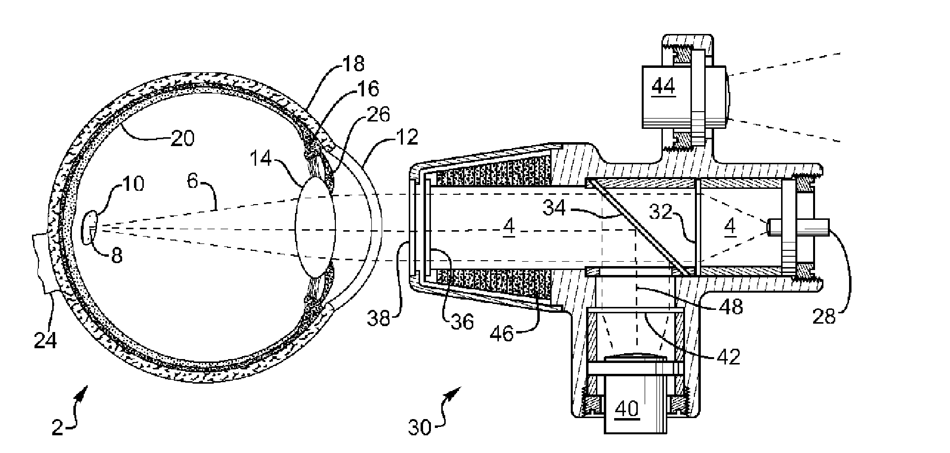
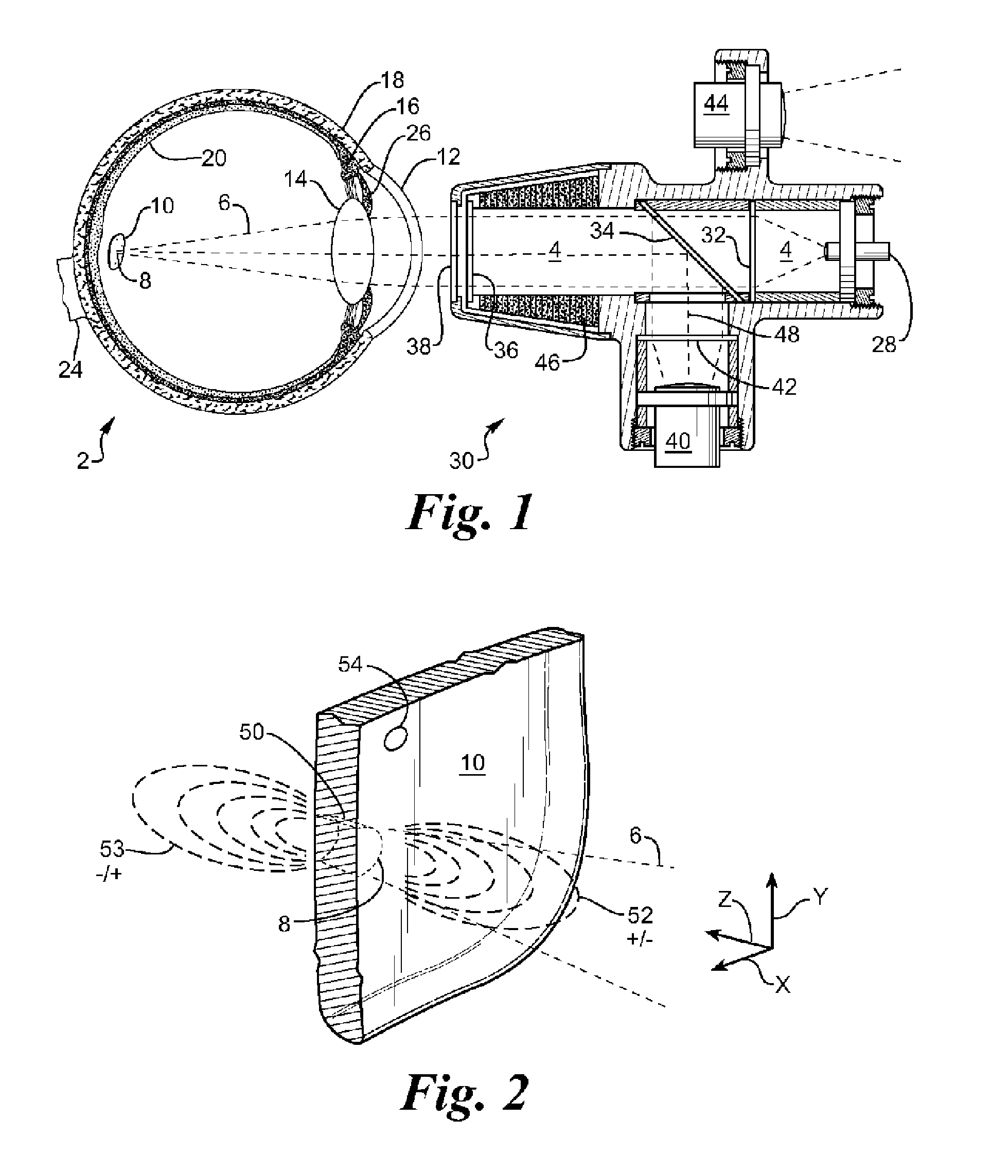
[0030]“Pyrode,” a term coined for the present invention, is an intended concatenation of “pyro” (fire) and “electrode.” Pyrode is defined herein as a body of solid, electrically non-conducting matter having a surface onto which an external source impinges a pulse of photonic energy (sudden feeble warming) that is converted internal to said body into an intense electric field manifested external to and proximate said surface.

[0031]FIG. 1 depicts a cross section of a pyrode embodiment configured as a system for partial restoration of vision, consisting of scanner assembly 30 and an eye 2 having pyrode 10 implanted in retina 20. It is emphasized that this is a complete stimulating system consisting of only pyrode 10 implanted in the eye, and a scanning assembly 30 located entirely outside the eye, with no connection therebetween other than a photonic connection. Light source 28 directs near-infrared rays 4 through field lens 32, through beam splitter 34, through scanning lens 36, throu...


PUM


Abstract

A pyrode converts near-infrared light to an electric field that wirelessly stimulates nerve tissue at one or more locations in a host body, such as in a retina, a cochlea, a heart axon, or a motor nerve. Partial vision is restored when a pyrode implanted in a retina is activated by a scanner. Only the pyrode is implanted in the retina, whereas all other components remain external to the host body. Nerves other than the retina are stimulated by a pyrode coupled to a source of photonic energy by an optical conduit. In one preferred embodiment the photonic energy source is implanted in the host body. In another preferred embodiment, photonic energy from an external source is piped to the pyrode by way of an optical conduit via a percutaneous lead. Electrooptic diverters enable sequential activation of multiple pyrodes branched from a main conduit.

Description

BACKGROUND OF THE INVENTION [0001]1. Field of the Invention[0002]This invention relates to photonic apparatus implanted in the body for stimulation of nerve tissue.[0003]2. Description of Related Art[0004]“Pyrode,” a term coined for the present invention, is an intended concatenation of “pyro” (fire) and “electrode.” Pyrode is defined herein as a body of solid, electrically non-conducting matter having a surface onto which an external source impinges a pulse of photonic energy (sudden feeble warming) that is converted internal to said body into an intense electric field manifested external to and proximate said surface.[0005]Functional neural tissue, while remaining responsive to stimulation, is known to become disconnected from the nervous system, but may be reactivated when properly stimulated, for example by a pulsed electric field. Stimulators of the prior art rely on an electrical conductor to carry pulses from an electric generator to the stimulation site, and on a metallic el...

Claims


Application Information

Patent Timeline
IPC IPC(8): A61F9/007A61N1/04
CPCA61N1/36046A61N1/3787A61N1/37211A61N1/362
Inventor CULP, GORDON W.
Owner CULP GORDON W
Why Eureka
Try Eureka