
Fuel injection method for internal-combustion engine, notably of direct injection type, comprising a piston provided with a bowl and a teat

a fuel injection and internal combustion engine technology, which is applied to the components of engines, machines/engines, pistons, etc., can solve the problems of poor use of the air contained in the combustion chamber, significant drawbacks in the layout, and the effect of reducing the number of injections

Inactive Publication Date: 2007-07-19
INST FR DU PETROLE
View PDF14 Cites 17 Cited by
  • Summary
  • Abstract
  • Description
  • Claims
  • Application Information

AI Technical Summary

Benefits of technology

The present invention is about a method of injecting fuel into a direct-injection four-stroke internal-combustion engine that can run in both a homogeneous combustion mode and a conventional combustion mode. The method involves injecting a first amount of fuel during the intake phase and a second amount of fuel during the compression phase. This method can be implemented by introducing the first amount of fuel in at least one injection and can be targeted for positions between 0° to 50° crank angle. The first amount of fuel can be between 2% and 10% of the total amount of fuel provided for the intake and compression phases. This method can improve engine performance and fuel efficiency.

Problems solved by technology

This layout, although satisfactory, involves some significant drawbacks.
This results in a bad use of the air contained in the combustion chamber, notably in the squish zone.

Method used


Image

  • Fuel injection method for internal-combustion engine, notably of direct injection type, comprising a piston provided with a bowl and a teat
  • Fuel injection method for internal-combustion engine, notably of direct injection type, comprising a piston provided with a bowl and a teat
  • Fuel injection method for internal-combustion engine, notably of direct injection type, comprising a piston provided with a bowl and a teat

Examples


Embodiment Construction

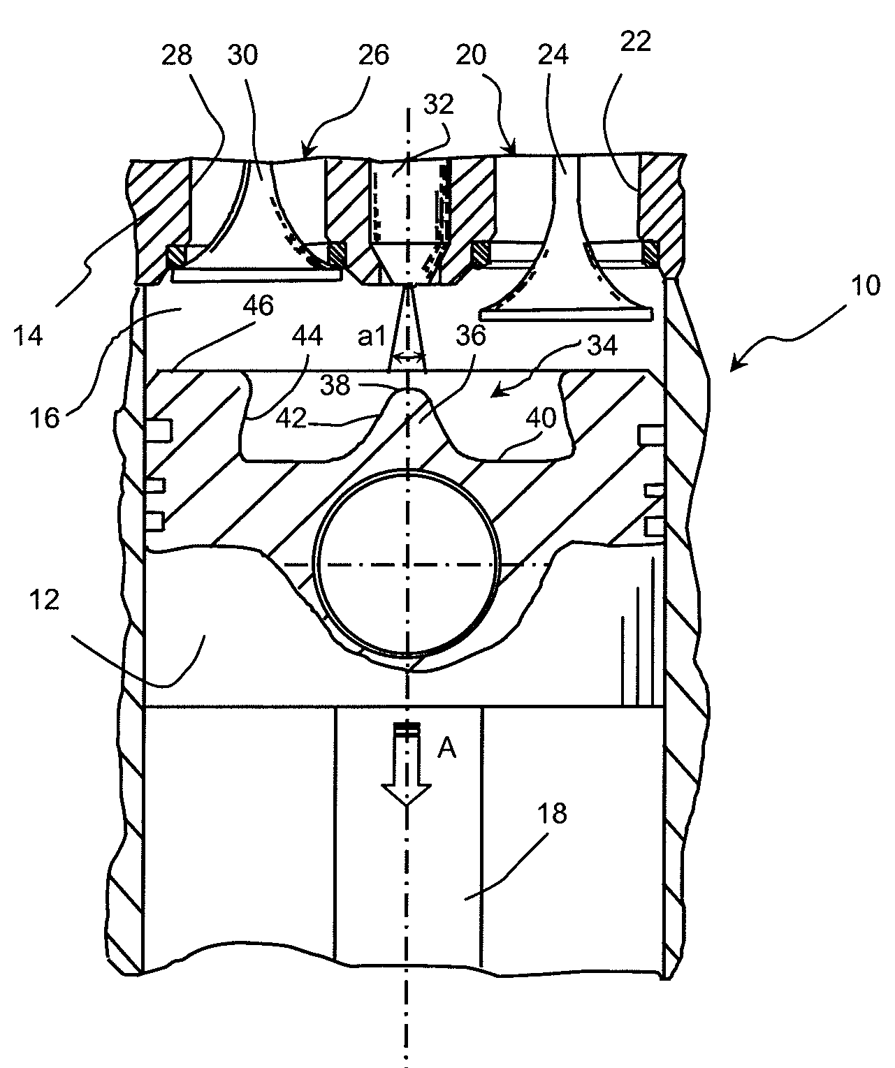
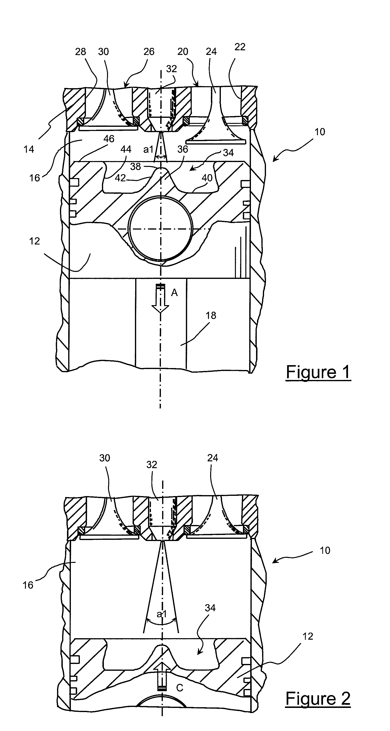
[0017] The engine of FIG. 1 is a non limitative example illustrating a type of four-stroke internal-combustion engine, notably of diesel type, that can run according to two combustion modes, a homogeneous mode and a conventional mode.

[0018] This engine comprises at least one cylinder 10, a piston 12 that slides within this cylinder in a reciprocating rectilinear motion and a cylinder head 14 that shuts off the top of the cylinder. This piston delimits, with the lateral wall of the cylinder and the surface of the cylinder head opposite, a combustion chamber 16 within which combustion of a fuel mixture can take place when the conditions for such a combustion are met. This piston is connected by a rod 18 to a crankshaft (not shown) and it therefore oscillates through the action of this crankshaft between an upper position referred to as top dead centre (TDC), where the combustion chamber occupies a limited volume, and a lower position referred to as bottom dead centre (BDC), where the...


PUM


Abstract

The present invention relates to a method of injecting fuel into the combustion chamber (16) of a cylinder of a direct-injection four-stroke internal-combustion engine, notably of diesel type, that can run according to a homogeneous combustion mode and according to a conventional combustion mode. According to the invention, this method consists, for the conventional combustion mode of the engine, in feeding into this chamber a first amount of fuel in the vicinity of the top dead centre of the piston at the beginning of the intake phase and another quantity of fuel in the vicinity of the top dead centre of this piston at the end of the compression phase.

Description

FIELD OF THE INVENTION [0001] The present invention relates to a fuel injection method for an internal-combustion engine, notably of direct injection type, in particular a diesel engine, with a piston provided with a bowl comprising a teat. [0002] It more particularly relates to a four-stroke diesel type direct-injection engine that can run according to two combustion modes. A mode referred to as homogeneous, better known as “Homogeneous Charge Compression Ignition” (H.C.C.I.), that is used for low and medium engine loads, with at least one fuel injection during compression. This or these injections allow to obtain homogeneous mixing of the fuel with air or with a mixture of air and of recirculated exhaust gas, before combustion starts by self-ignition. The other combustion mode, referred to as conventional combustion mode, consists of a fuel injection in the vicinity of the compression top dead centre and of a diffusion combustion, this mode being preferably used at high loads. BAC...

Claims


Application Information

Patent Timeline
Patent Type & Authority Applications(United States)
IPC IPC(8): F02F3/26F02B3/00
CPCF02B1/12F02B3/06F02B23/0669F02B23/0672Y02T10/123F02D41/3035F02D41/403Y02T10/44F02B2275/14Y02T10/12Y02T10/40F02D41/38F02D41/30F02F3/26
Inventor WALTER, BRUNO
Owner INST FR DU PETROLE
Learn More