Hybrid vehicle

a hybrid vehicle and hybrid technology, applied in the field of hybrid vehicles, can solve the problems of increasing power consumption and reducing energy recovery efficiency, and achieve the effects of reducing friction, reducing power consumption, and improving energy recovery efficiency

Inactive Publication Date: 2007-07-19
HONDA MOTOR CO LTD
View PDF13 Cites 18 Cited by
  • Summary
  • Abstract
  • Description
  • Claims
  • Application Information

AI Technical Summary

Benefits of technology

[0012] In accordance with the first aspect, since the driving force of the generator / motor, which is disposed so as to surround the outer periphery of the axis of the input shaft of the transmission, is transmitted to any position of the power transmission pathway between the output shaft of the transmission and the differential gear via the power transmission means, it is possible to carry out leg shaft drive in which transmission of the driving force between the generator / motor and the differential gear is carried out without going through the engine and the input shaft, power consumption can be reduced due to a decrease in friction, and the energy recovery efficiency during regenerative braking can be improved. Furthermore, since the crankshaft of the engine and the input shaft of the transmission are disposed coaxially, and the generator / motor is disposed at a position sandwiched between the engine and the transmission, the generator / motor can be arranged in the same manner as for a conventional sandwiched generator / motor type, and not only can the leg shaft drive system be employed without greatly modifying the design of the sandwiched generator / motor type transmission, but also the axial dimension does not increase compared with the sandwiched generator / motor type transmission.
[0013] In accordance with the second aspect, since the generator / motor is disposed coaxially with the axis of the input shaft, it is possible to easily avoid interference between the generator / motor and the input shaft.
[0014] In accordance with the third aspect, since the starter motor is joined to the end part of the input shaft on the side opposite to the engine side, the engine can be started by means of a compact structure, and power can be generated by driving the starter motor by means of the engine.
[0015] In accordance with the fourth aspect, since the starter motor disposed so as to surround the axis of the input shaft at a position sandwiched between the engine and the transmission is joined to the crankshaft or the input shaft, the engine can be started by means of a compact structure, and power can be generated by driving the starter motor by means of the engine.
[0016]FIG. 1 is a vertical sectional view of a power unit of a hybrid vehicle related to a first embodiment (Embodiment 1).
[0017]FIG. 2 is an enlarged view of part A in FIG. 1 (Embodiment 1).

Problems solved by technology

In the layout of the sandwiched generator / motor type, since the generator / motor is joined to a crankshaft of the engine and an input shaft of the transmission and always rotates integrally therewith, when the generator / motor carries out regenerative braking during deceleration of the vehicle, there are the problems that friction in the engine and the transmission might degrade the energy recovery efficiency, and the friction of the engine is a load on the generator / motor when traveling by means of the generator / motor, thus increasing the power consumption.

Method used


Image

  • Hybrid vehicle
  • Hybrid vehicle
  • Hybrid vehicle

Examples


embodiment 1

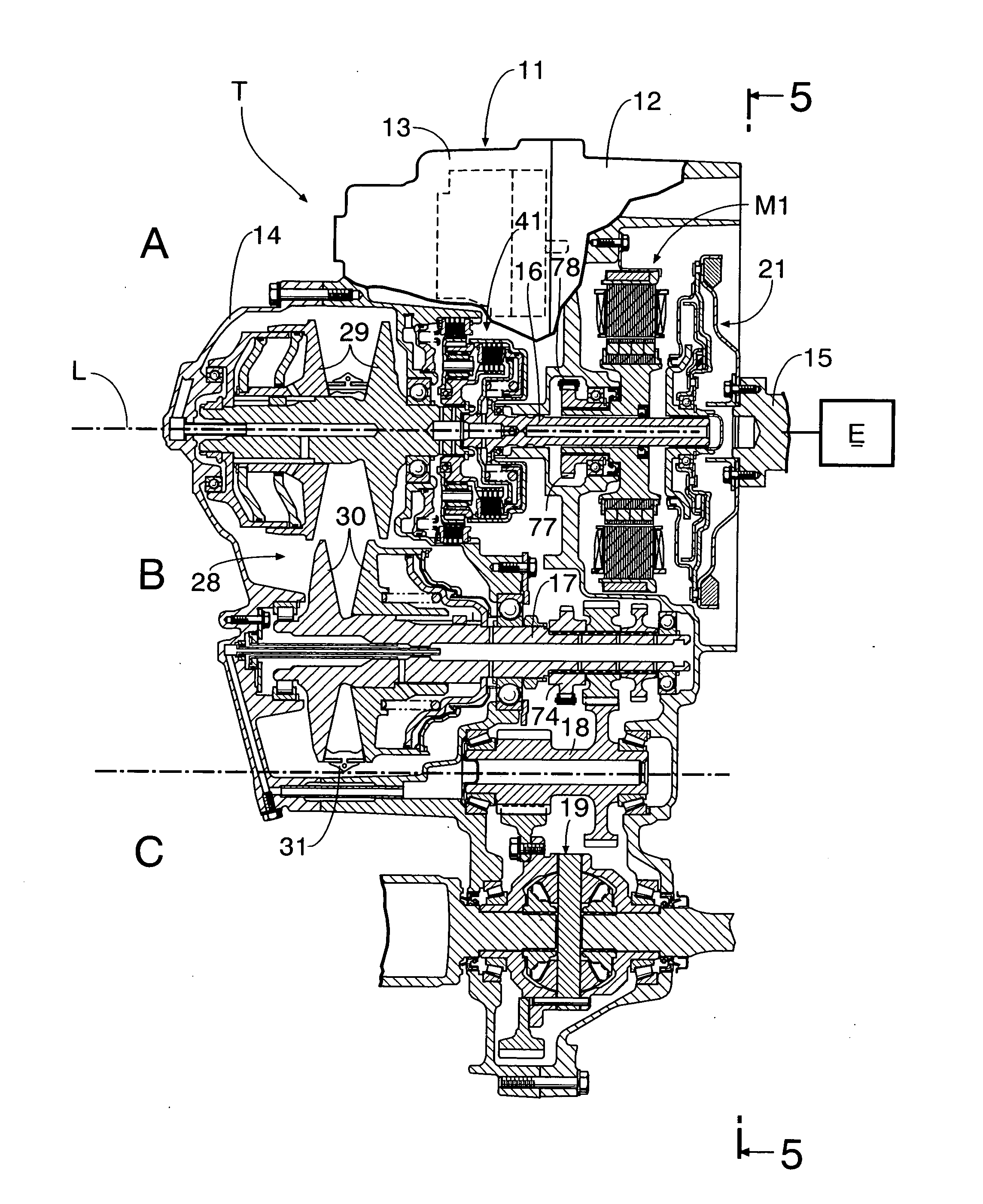
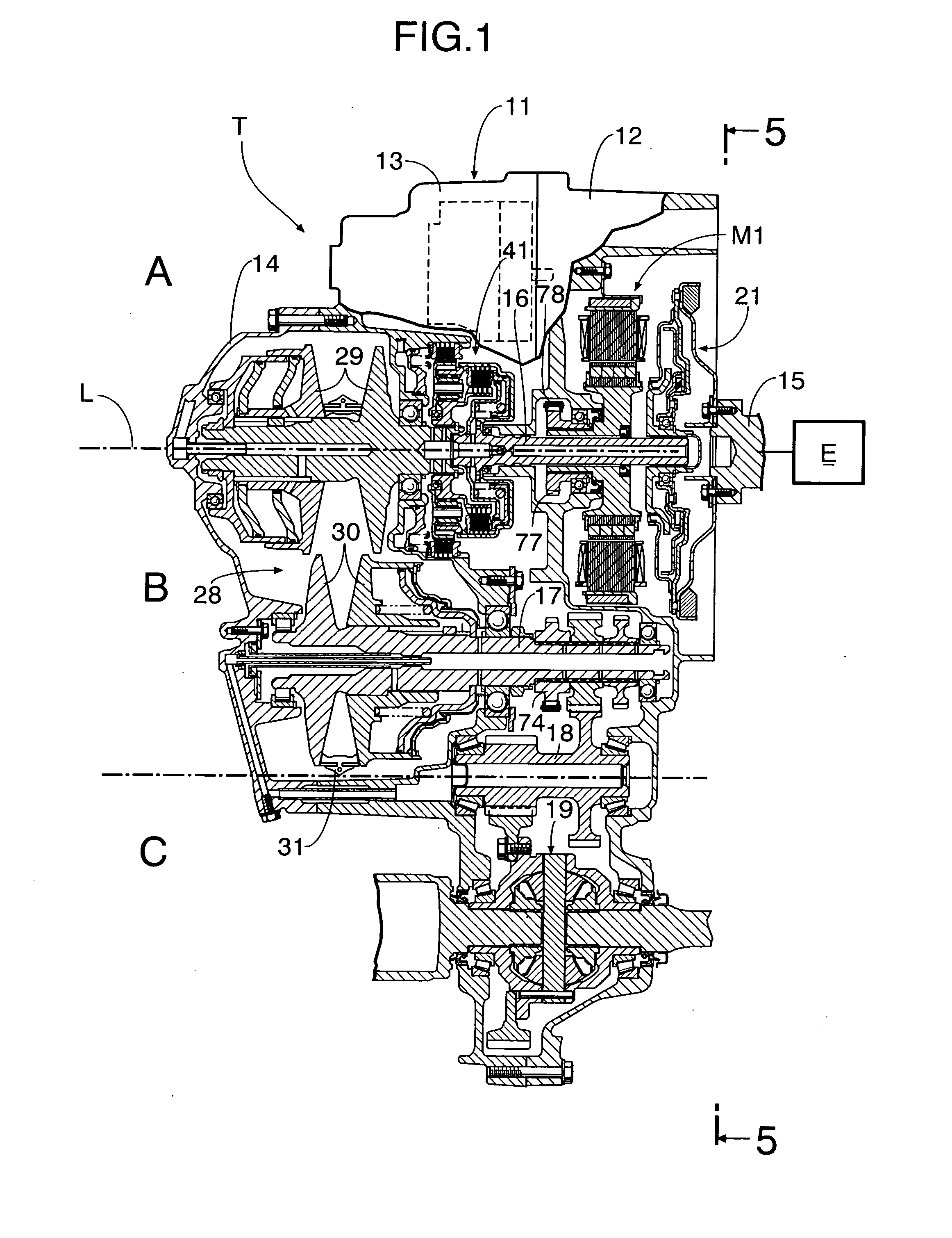
[0037]FIG. 1 to FIG. 6 show a first embodiment of the present invention.

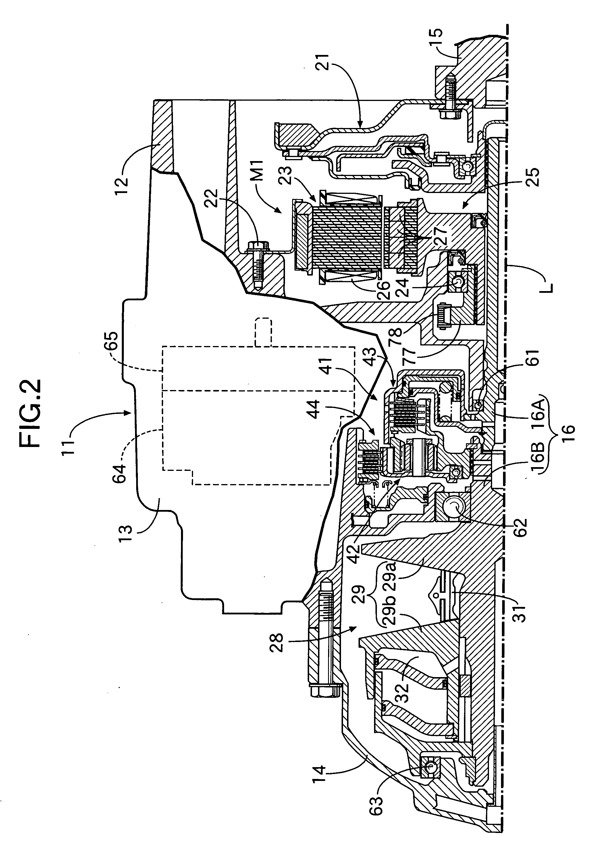
[0038] As shown in FIG. 1, a transmission case 11 of a transmission T mounted in a front part of a vehicle body of a front-engined / front wheel drive vehicle is divided into a right casing 12, a middle casing 13, and a left casing 14. A shaft end of a crankshaft 15 of an engine E faces an opening at the right-hand end of the right casing 12, and an input shaft 16 (main shaft) of the transmission T, which shares an axis L with the crankshaft 15, is supported in the interior of the transmission case 11. Furthermore, supported within the transmission case 11 are an output shaft 17 (counter shaft) and a reduction shaft 18, which are parallel to the input shaft 16, and disposed beneath the reduction shaft 18 is a differential gear 19.

[0039] As is clear from FIG. 5, the output shaft 17 is disposed above and behind the crankshaft 15 and the input shaft 16, which are disposed on the axis L, the reduction shaft 18 is di...

embodiment 2

[0057]FIG. 7 and FIG. 8 show a second embodiment of the present invention.

[0058] A transmission T of the second embodiment is different from the first embodiment in that it is equipped with a starter motor M2 for directly driving a crankshaft 15 so as to start an engine E, the remainder of the structure being the same as that of the first embodiment.

[0059] That is, the starter motor M2 is formed from a stator 102 fixed to a right casing 12 via bolts 101, and a rotor 103 fixed to a shaft end of the crankshaft 15, the stator 102 being provided with a plurality of coils 104, and the rotor 103 being provided with a plurality of permanent magnets 105.

[0060] Therefore, driving the starter motor M2 allows the rotor 103 to crank the crankshaft 15, thus starting the engine E. Furthermore, since the rotor 103 of the starter motor M2 has a sufficient weight, it is unnecessary to mount a mass on a damper 21 and it is possible to make the rotor 103 function as a flywheel.

[0061] Since a gener...

embodiment 3

[0064] The third embodiment does not include the forward / reverse travel switching mechanism 41, but instead is provided with an input shaft clutch 111 and a starting clutch 112 on an input shaft 16 and an output shaft 17 respectively. The input shaft clutch 111 can couple the left-hand end of the input shaft 16 to a drive pulley 29 of a belt type continuously variable transmission 28. Furthermore, the starting clutch 112 can couple a first reduction gear 75 to the output shaft 17.

[0065] In accordance with the third embodiment, engaging both the input shaft clutch 111 and the starting clutch 112 enables forward travel by means of the engine E. However, since the forward / reverse travel switching mechanism 41 is not included, reversing by means of the engine E is not possible. On the other hand, driving a generator / motor M1 forward and in reverse enables forward travel and reverse travel by means of the leg shaft drive. In this process, by disengaging the starting clutch 112 the drivi...


PUM


Abstract

A hybrid vehicle is provided in which, since the driving force of a generator/motor (M1) disposed so as to surround the outer periphery of an input shaft (16) of a transmission (T) is transmitted to an output shaft (17) of the transmission (T) via an endless chain (78), it is possible to carry out the so-called leg shaft drive, in which transmission of the driving force between the generator/motor (M1) and the output shaft (17) is carried out without going through an engine (E) and the input shaft (16), thus reducing power consumption and enhancing energy recovery efficiency during regenerative braking. Furthermore, since a crankshaft (15) of the engine (E) and the input shaft (16) of the transmission (T) are disposed coaxially, and the generator/motor (M1) is disposed at a position sandwiched between the engine (E) and the transmission (T), it is possible to employ the same layout for the generator/motor (M1) as for a conventional sandwiched generator/motor, and the leg shaft drive system can be employed without greatly modifying the design of the transmission (T).

Description

TECHNICAL FIELD [0001] The present invention relates to a hybrid vehicle that can travel by means of either one or both of the driving force of an engine and the driving force of a generator / motor. BACKGROUND ART [0002] In such a hybrid vehicle, the layout for an engine, a generator / motor, and a transmission that is conventionally employed is in general of a so-called sandwiched generator / motor type in which a thin generator / motor is sandwiched between the engine and the transmission. In the layout of the sandwiched generator / motor type, since the generator / motor is joined to a crankshaft of the engine and an input shaft of the transmission and always rotates integrally therewith, when the generator / motor carries out regenerative braking during deceleration of the vehicle, there are the problems that friction in the engine and the transmission might degrade the energy recovery efficiency, and the friction of the engine is a load on the generator / motor when traveling by means of the ...

Claims


Application Information

Patent Timeline
Patent Type & Authority Applications(United States)
IPC IPC(8): B60K1/00B60K5/04B60K6/26B60K6/36B60K6/40B60K6/44B60K6/48B60K6/543B60K17/04B60L50/16
CPCB60K5/04B60K6/26B60K6/365B60K6/40Y02T10/92B60K6/485B60K6/543Y02T10/6221Y02T10/6226B60K6/48B60L2240/486B60L50/15Y02T10/62Y02T10/7072Y10S903/906
Inventor ABE, NORIYUKIKIMURA, HIDEOFUCHINO, MASAYUKIHASEBE, TETSUYA
Owner HONDA MOTOR CO LTD
Why Eureka
Try Eureka