Flywheel drive system for a motor vehicle and method therefor

a technology of drive system and flywheel, which is applied in the direction of propulsion parts, electric propulsion mounting, transportation and packaging, etc., can solve the problems of large environmental pollution, flywheels have a fast recharge time, and the life of flywheels is almost unlimited with proper maintenance, so as to save stored energy in the flywheel, the effect of enhancing the capability

Inactive Publication Date: 2007-07-19
MANGANARO CARL
View PDF26 Cites 19 Cited by
  • Summary
  • Abstract
  • Description
  • Claims
  • Application Information

AI Technical Summary

Benefits of technology

[0010] To further enhance the capability of the present invention, in addition to the main generator, secondary generators are attached to the two front wheels, which provide additional current to the main generator when the vehicle is in motion, thus, saving the stored energy in the flywheel. Furthermore, the starter device causes the flywheel to rotate at a maximum speed, which allows the flywheel to reach maximum charge.

Problems solved by technology

Many people feel that disposing of the used car batteries may be a larger environmental problem than burning fossil fuels.
As compared to batteries, which have a limited number of charges before replacement, a flywheel will have an almost unlimited lifespan with proper maintenance, despite a large number of charge and discharge cycles.
Furthermore, flywheels have a fast recharge time as compared to batteries.
A large battery may take several hours to recharge, while a flywheel may take minutes.
While present flywheel systems for driving electric powered vehicles do currently work, they have several problems.
First, most electric vehicles are limited as to the speed the vehicle may travel.
The power provided by a single electric motor is generally limited due to the weight of the vehicle.
Furthermore, a single electric motor fails to provide sufficient power to satisfy most consumers.
Second, most flywheels are generally started by use of a battery.
However, if the battery should fail, most flywheel systems have no back-up power supply to start the flywheel.

Method used


Image

  • Flywheel drive system for a motor vehicle and method therefor
  • Flywheel drive system for a motor vehicle and method therefor
  • Flywheel drive system for a motor vehicle and method therefor

Examples


Embodiment Construction

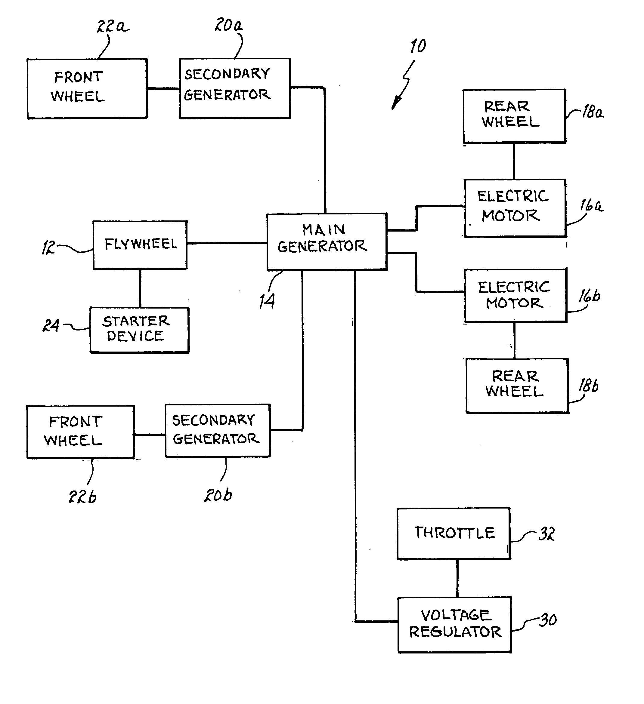
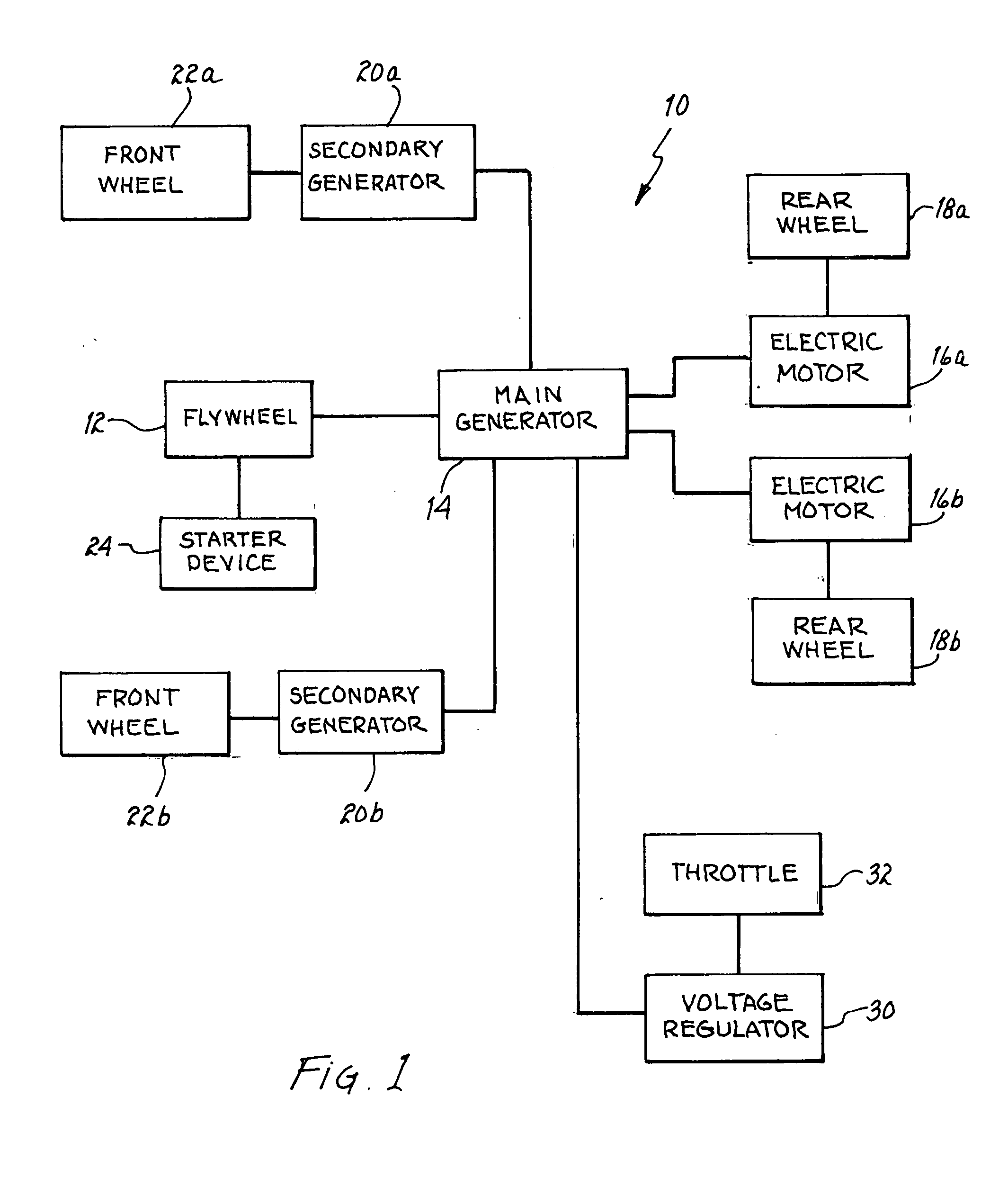
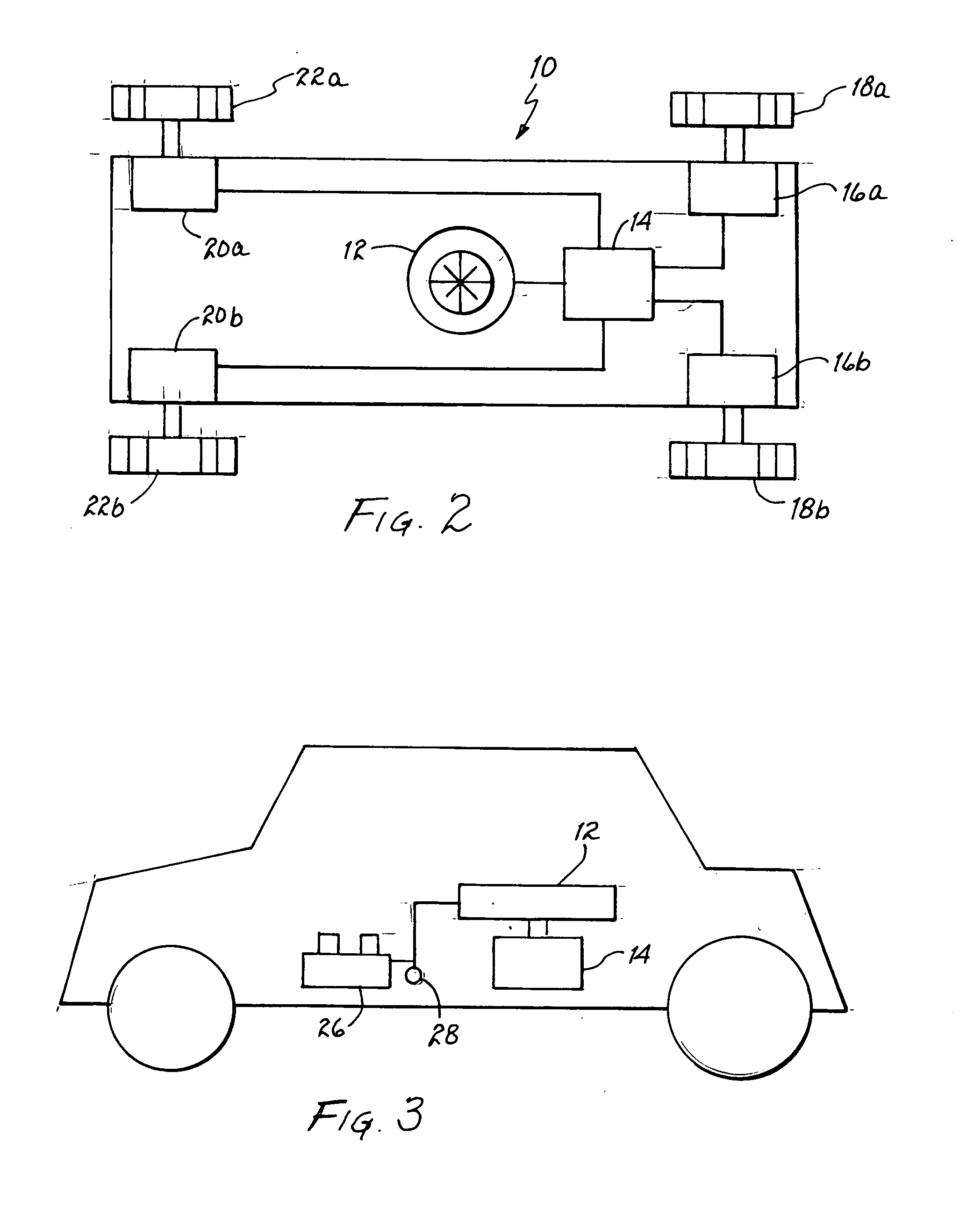
[0014] The present invention is a flywheel system that drives a motor vehicle. In one embodiment of the invention, the flywheel is a source of power for a main generator, which in turn powers electric motors placed at each rear wheel of the vehicle. The electric motors cause the rear wheels to rotate and drive the motion of the vehicle. Furthermore, generators placed at each front wheel provide additional current to the main generator when the vehicle is in motion, thus saving the energy stored within the flywheel.

[0015]FIG. 1 illustrates a block diagram of the flywheel drive system of the present invention 10 (hereinafter system 10). Included in the invention is a flywheel 12 that stores energy used by the system through constant rotation. As stated before, a flywheel 12 is a clean energy source without emissions that can be charged and re-charged numerous times. In the present invention, the flywheel 12 is made of high tensile spring wire or other filament and is placed within a ...


PUM


Abstract

An apparatus for generating an electric current to drive a vehicle has an electric motor coupled to each rear wheel of the vehicle. The electric motors are used to drive each rear wheel. A main generator is coupled to each electric motor. The main generator powers each electric motor. A flywheel is coupled to the main generator. The flywheel powers the main generator. A starter device is coupled to the flywheel. The starter device causes the flywheel to begin to rotate.

Description

BACKGROUND OF INVENTION [0001] 1. Field of Invention [0002] The present invention relates to a drive system for a motor vehicles and more specifically, to a flywheel design system that powers an electric motor for propelling a motor vehicle. [0003] 2. Description of Related Art [0004] In order to reduce the dependence on fossil fuels, alternative methods to drive motor vehicles need to be developed. One of the explored technologies is the use of electric motors in automobiles. Electric motors generally are powered by a DC power source such as a battery and do not require the use of gasoline or diesel fuel. One benefit of using electric motors is that they do not emit pollutants into the atmosphere since they do not burn fossil fuels. Electric motors provide a clean source of power to propel a motor vehicle. [0005] One requirement of electric motors is the need for a large energy storage system to provide continuous power. One solution has been to use car batteries to power the elect...

Claims


Application Information

Patent Timeline
Patent Type & Authority Applications(United States)
IPC IPC(8): B60K1/00
CPCB60K7/0007B60L11/16Y02T10/7027Y02T10/7033Y02T10/648Y02T10/646B60L50/30Y02T10/70Y02T10/64
Inventor MANGANARO, CARL
Owner MANGANARO CARL
Why Eureka
Try Eureka