
Pouring apparatus for carbonated beverages in bottles

a technology for pouring apparatus and carbonated beverages, which is applied in the direction of liquid handling, closure using stoppers, caps, etc., can solve the problems of low cost, situation can occur, and special “bubbly” character of beverages, and achieve the effect of low cos

Inactive Publication Date: 2007-07-19
BURKOVSKIY IGOR
View PDF18 Cites 11 Cited by
  • Summary
  • Abstract
  • Description
  • Claims
  • Application Information

AI Technical Summary

Benefits of technology

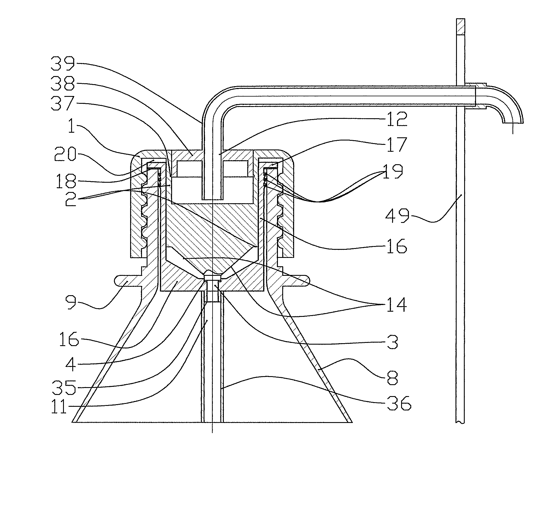
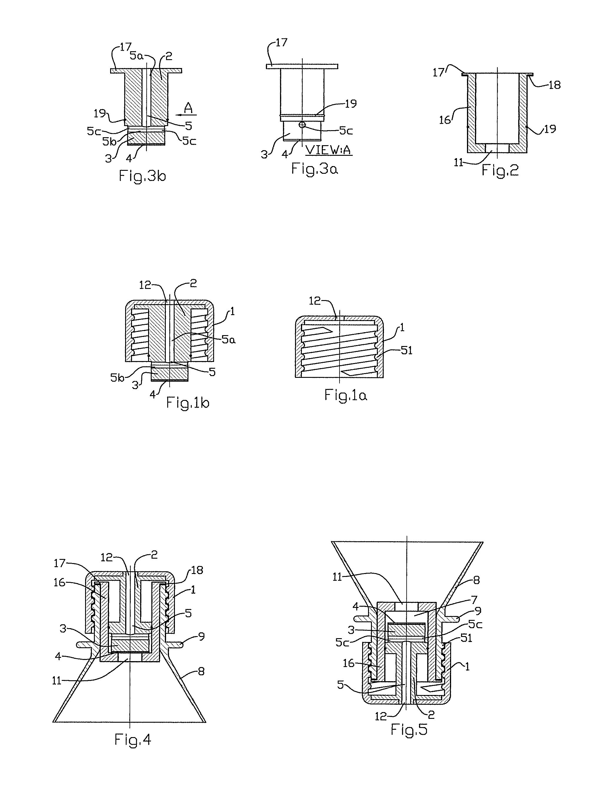
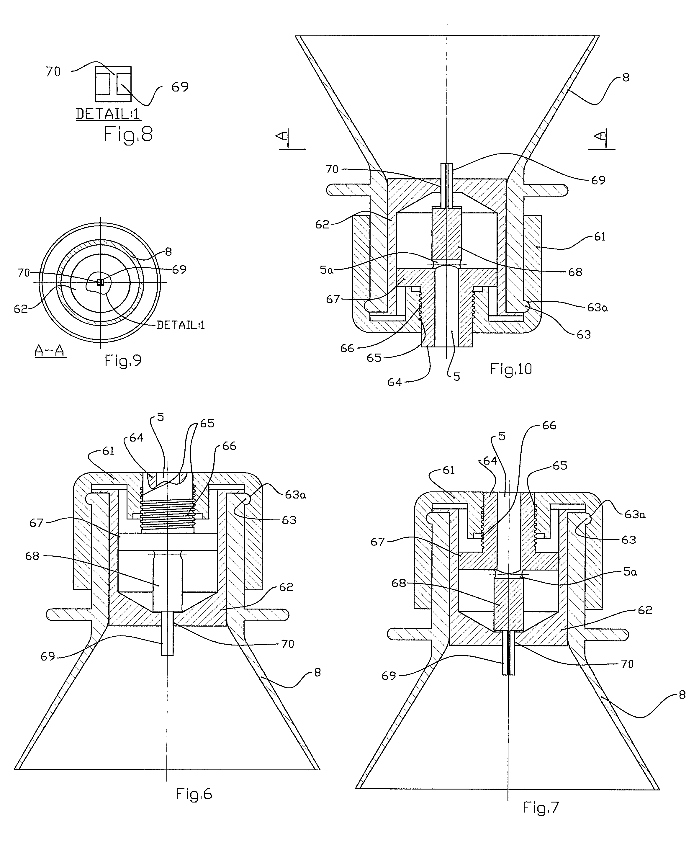
[0008] The invention is based on the principle of a cylinder and a piston. The cylinder is placed inside a bottle containing a carbonated beverage, such as soda, beer or sparkling wine. Alternatively, the structural features of the “cylinder” can be imparted onto the bottle during the manufacturing process, with the same functional result. The cylinder forms a double neck for the bottle and remains fixed in position. An opening in the bottom of the cylinder allows the beverage (and the pressurized gas dissolved within the beverage) to pass into the chamber of the cylinder and toward the mouth of the bottle, when the beverage is consumed or dispensed. A gasket placed around the outer circumference of the cylinder places it firmly within the neck of the bottle and prevents passage of beverage or pressurized gas around the outside of the cylinder.
[0009] The piston fits snugly inside the cylinder for most of its length, and a gasket placed around the outer circumference of the piston assures a tight fit inside the inner circumference of the cylinder. Within the piston is a T-shaped tubular path (in the preferred embodiment) with a vertical component running concentrically with the piston for most of its length. A horizontal component of the tubular path is located near the bottom of the cylinder, with openings diametrically oriented on the wall of the piston. The piston is narrower at its tip, where the openings are located, than along the rest of its length. This allows the beverage and gas to enter the T-shaped tubular path in the piston, prior to being poured from the bottle.

Problems solved by technology

Beer and sparkling wines have been consumed for centuries, but the entire bottle must be consumed immediately upon opening, or the special “bubbly” character of the beverage is lost.
This gas pressure can also cause the beverage to be rapidly ejected from the bottle in which it had been contained, causing a mess.
This situation can occur especially if beer or sparkling wine is not handled properly.
Other means for bottle closure known in the art (e.g. Ladina, U.S. Pat. No. 6,474,515 (2002)) are useful for preventing spraying of non-carbonated beverages, but are not as useful for keeping the pressurized gas within a beverage bottle, specifically a soda bottle.

Method used


Image

  • Pouring apparatus for carbonated beverages in bottles
  • Pouring apparatus for carbonated beverages in bottles
  • Pouring apparatus for carbonated beverages in bottles

Examples


Embodiment Construction

[0077] The principle behind the invention described here is simple. An apparatus is placed inside the neck of a bottle which contains a carbonated beverage. This apparatus allows the beverage to be dispensed as desired, while retaining most of the pressurized gas inside the bottle. This allows the beverage to retain its “fizz” from the time the first sip is consumed until the last sip is consumed.

[0078] The apparatus is cylindrical in shape, and comprises a cylinder and a piston. In the practice of the invention, the piston is attached to a cap, which is fitted onto the bottle by means known in the conventional art. FIG. 4 shows a partial cutaway view of the invention in use, while the bottle is closed, holding the beverage inside. Cap 1 sits on top of Bottle 8 in the usual manner, the inside threads of Cap 1 engaging the outside threads on Bottle 8. The visible difference between the present invention and a conventional soda bottle is Opening 12, located at the top of Cap 1. In th...


PUM


Abstract

The present invention comprises an apparatus which, when inserted into the neck of a bottle, facilitates the dispensing of carbonated beverages such as soda, beer and sparkling wines. The invention does so in a manner that prevents spillage of a carbonated beverage, while retaining the gas that gives the beverage its “fizz” within the bottle into which the beverage was originally placed. The cap valve, which creates a water tap inside the bottleneck maintains a secure seal that prevents material from escaping, even if the contents are under pressure. The cap functions like a faucet that opens or closes upon rotation. In the open state it regulates outflow and has structural safeguards to prevent accidental removal from the bottleneck. To put a secure seal on the bottle, the cap presses against the double neck outlet with its valve that has a gasket. Between the end of the moving part that directs the flow in the double neck and the inside of the cap exists a locking space, which enables the valve to securely cover the double neck outlet upon application of pressure by the cap on the bottle, thus impeding outflow. When the cap is unscrewed from the bottle, the valve frees the double neck outlet, creating a passageway that enables outflow of the container's contents. If the bottle contains carbonated liquids, the best method for pouring involves holding the container in such a way that its bottom is higher than the cap and the liquid covers the valve. Because liquid is heavier than gas, only liquid will flow through the cap's open valve. The rest of the gas will remain in the container. This will markedly improve the quality of carbonated soft drinks or similar products. There are added optional features to enable a user to drink directly from the bottle by utilizing: (1) a cone like cup or (2) a tube and nipple configuration.

Description

[0001] This application claims the benefit of earlier files, Provisional Application US60 / 750,513, dated Dec. 15, 2005FIELD OF THE INVENTION [0002] The present invention comprises an apparatus which, when inserted into the neck of a bottle, facilitates the dispensing of carbonated beverages such as soda, beer and sparkling wines. The invention does so in a manner that prevents spillage of a carbonated beverage, while retaining the gas that gives the beverage its “fizz” within the bottle into which the beverage was originally placed. BACKGROUND OF THE INVENTION [0003] Carbonated beverages are extremely popular. Soda retains its popularity among the products with the largest sales nationally. Beer and sparkling wines have been consumed for centuries, but the entire bottle must be consumed immediately upon opening, or the special “bubbly” character of the beverage is lost. One feature common to all carbonated beverages is the presence of a gas, typically carbon dioxide, imparted into t...

Claims


Application Information

Patent Timeline
IPC IPC(8): B65D35/38B65D51/16
CPCB67D3/0061
Inventor BURKOVSKIY, IGOR
Owner BURKOVSKIY IGOR
Learn More