
Rotatable tool and apparatus therefor

a technology of rotating tools and fsw equipment, which is applied in the direction of manufacturing tools, soldering devices, and auxillary welding devices, etc., can solve the problems of large size and payload of existing fsw equipment, and large cost of such equipment compared to equipment, so as to facilitate the significantly compact structure of fsw equipment and more accurate depth control

Active Publication Date: 2007-07-19
TOL O MATIC
View PDF3 Cites 23 Cited by
  • Summary
  • Abstract
  • Description
  • Claims
  • Application Information

AI Technical Summary

Benefits of technology

[0009] The present invention relates generally to linearly moveable apparatus and tools or devices with rotating or selectively rotatable tool heads such as tools or devices for friction stir welding, machining / milling, boring / drilling, routing, screw fastening and lift and rotate operations. More specifically, the preferred embodiment of the present invention relates to a compact, low cost servo driven friction stir weld (FSW) apparatus and device that has particular applicability for spot and / or stitch welding. As used herein, stitch welding is essentially spot welding with a short travel distance, typically an inch or less.
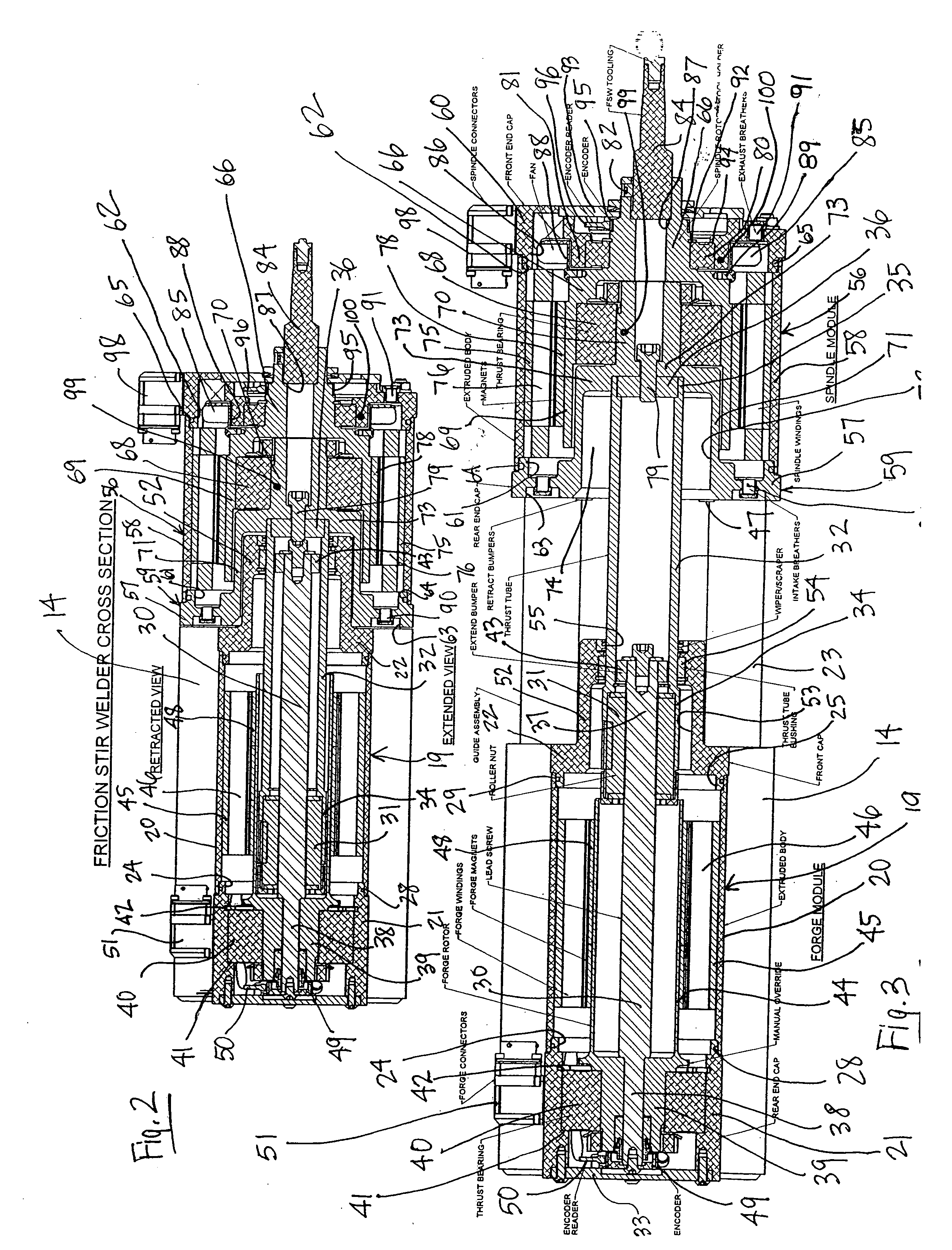
[0012] The FSW spindle or device module includes a tool head appropriate for spot and / or stitch welding and a motor for rotating the FSW tool head. Preferably, the motor for the FSW module is an inline motor with its center of rotation concentric with the rotational center of the tool head. More preferably, the motor is a hollow core, inline motor. The FSW module further includes a housing which minimizes the overall size and length of the friction stir welding apparatus and thus facilitates an extremely compact FSW apparatus and system. Specifically, the FSW device housing includes a rear end cap which defines an internal nesting cavity partially positioned internally within the FSW motor. This nesting cavity enables a portion of the forward end or end cap of the actuator module to nest within this cavity when the FSW module is in its retracted position, thereby resulting in an extremely compact apparatus.
[0015] The FSW module is also provided with thermal or temperature sensors for sensing and monitoring FSW component temperatures. This temperature information allows the linear axis motion control system to compensate for thermal expansion of such components to provide for more accurate depth control.
[0016] In the preferred embodiment, the actuator module and the FSW module are mounted relative to one another so that the rotational axes of their respective motors are inline or concentric with one another and so that the thrust member is connected with the FSW module immediately adjacent to or within the FSW spindle motor. More preferably, the forward end of the actuator module housing and the rearward end of the FSW module housing are configured so that they are capable of nesting with one another when the FSW module is retracted. This facilitates the significantly compact structure of the FSW apparatus.

Problems solved by technology

The process involves applying a rotating tool or tool head of various configurations to the abutting faces of two or more workpieces, thereby generating frictional heat.
While the use of friction stir spot welding has significant potential applicability for use in the automotive and these various other industries, it also faces several obstacles.
These include, among others, the large size and payload of existing FSW equipment and the cost of such equipment as compared to equipment for other conventional joining or spot welding techniques.

Method used


Image

  • Rotatable tool and apparatus therefor
  • Rotatable tool and apparatus therefor
  • Rotatable tool and apparatus therefor

Examples


Embodiment Construction

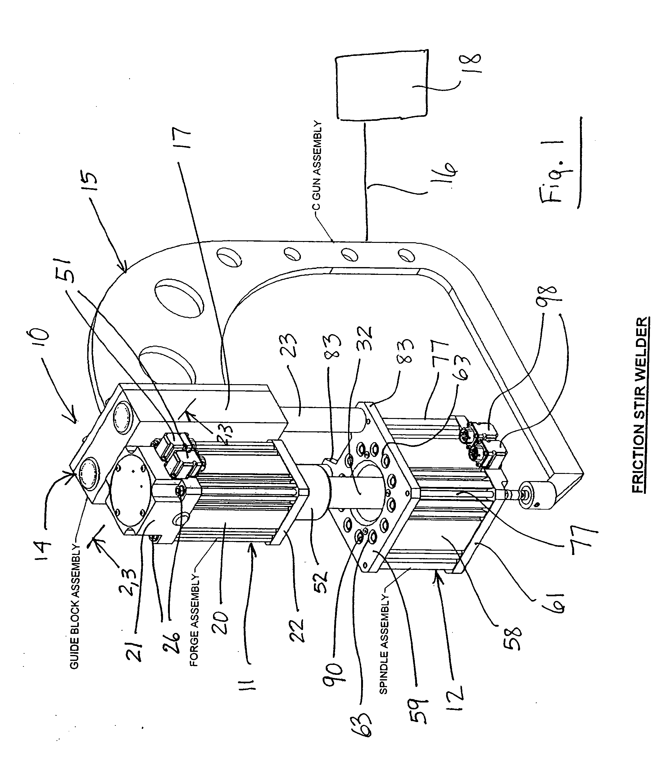
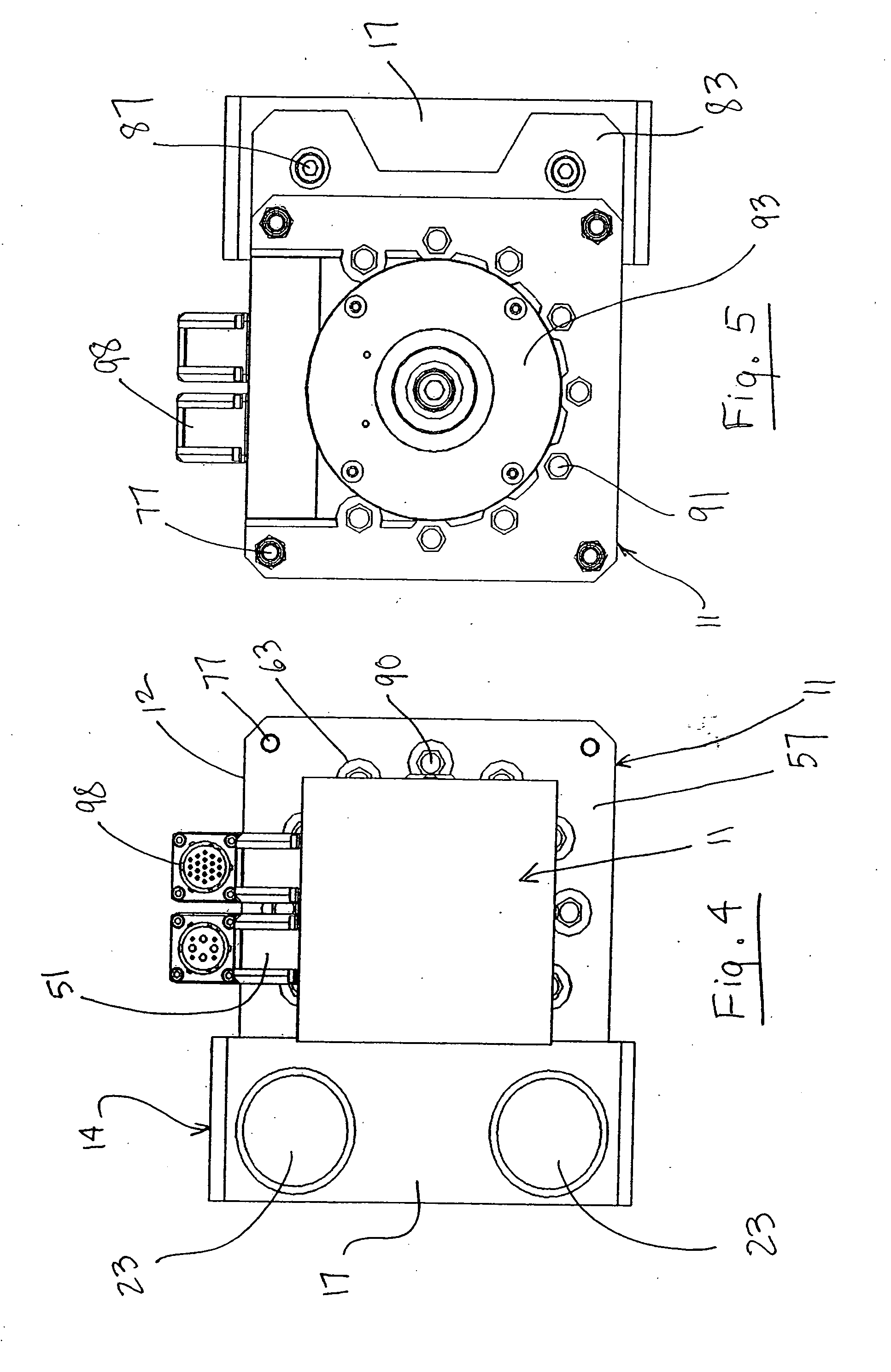
[0033] With reference first to FIG. 1, the friction stir weld apparatus or assembly 10 in accordance with the present invention includes a forge or actuator module 11, a friction stir weld spindle or device module 12, a guide or guide block module 14 and a “C” gun assembly 15. As shown schematically, the “C” gun assembly 15 is connected via conventional articulation joints and links 16 to a conventional industrial robot 18. Alternatively, the apparatus may be used in a pedestal application where it is mounted fixed to a table or framework. In the preferred embodiment as shown, the guide block assembly 14 is rigidly connected to the “C” gun assembly 15 and the actuator assembly 11 is rigidly connected to the guide block assembly 14. The FSW spindle module 12 is connected with a linear thrust tube portion of the actuator module 11. The FSW module 12 is also connected to guide shafts or rods 23 of the block assembly 14 and is thus guided for linear movement relative to the module 11 vi...


PUM


Abstract

A friction stir weld apparatus having a linear drive actuator and a separate friction stir weld device. The linear actuator and the friction stir weld device are driven by concentric motors. In the preferred embodiment, the thrust member of the actuator is connected to the friction stir weld device within or adjacent to the friction stir weld device motor to advance and retract the friction stir weld deice along a linear axis concentric with the actuator and friction stir weld device motors.

Description

BACKGROUND OF THE INVENTION [0001] 1. Field of the Invention [0002] The present invention relates to a rotatable tool and apparatus therefor, and more specifically to a rotatable, linearly moveable tool and apparatus such as an apparatus and device for friction stir spot and / or stitch welding. [0003] 2. Description of the Prior Art [0004] Various tools or devices with rotatable tool heads are also linearly moveable, or designed for linear movement, between operative and non-operative positions or between various linear stages of operative positions. Examples include tools and devices for friction stir welding, machining / milling, boring / drilling, routing, screw fastening and lift and rotate operations, among others. Desired characteristics of all such tools and devices is that they exhibit excellent stability and balance and are as linearly compact as possible. Although the present invention has potential applicability to all of the above, it has particular applicability to friction ...

Claims


Application Information

Patent Timeline
Patent Type & Authority Applications(United States)
IPC IPC(8): B23K20/12
CPCB23K20/125B23K20/1235
Inventor HOCHHALTER, KEITHSEILER, MIKE T.TAYLOR, DREW O.
Owner TOL O MATIC
Learn More