
Helicopter

a helicopter and helicopter technology, applied in the field of helicopters, can solve the problems of complex machine, unstable helicopter, difficult control,

Inactive Publication Date: 2007-07-19
SILVERLIT TOYS MANUFACTORY
View PDF99 Cites 43 Cited by
  • Summary
  • Abstract
  • Description
  • Claims
  • Application Information

AI Technical Summary

Benefits of technology

[0008]Solutions to slow down the effect have already been provided up to now, including the application of stabilizing rods and weights at the tips of the propeller blades.
[0020]The present disclosure aims to minimize one or several of the above-mentioned and other disadvantages by providing a simple and cheap solution to auto stabilize the helicopter, such that operating the helicopter becomes simpler and possibly reduces the need for long-standing experience of the pilot.
[0026]In practice, it appears that such an improved helicopter is more stable and stabilizes itself relatively quickly with or without a restricted intervention of the user.
[0029]By measuring the relative angular displacement of the swing and by using the measured signal as an input signal for a microprocessor which controls the drive of the main rotor and the drive of the tail rotor as a function of a stabilizer algorithm, the thrust of the tail rotor can be adjusted so as to counteract the unwanted effect of the disturbance and to thus automatically restore the stable flight conditions for the helicopter, with minimal or any intervention of the pilot.
[0033]The propeller blades of the main rotor and the vanes of the auxiliary rotor respectively are connected to each other with a mechanical linkage that permits the relative movement between the blades of the propeller and the vanes of the auxiliary rotor.
[0034]There are wings directed transversely of a longitudinal axis of the helicopter body directed transversely and downwardly and a downwardly directed stabilizer at the tail of the helicopter. This facilitates stability on the ground.

Problems solved by technology

It known that a helicopter is a complex machine which is unstable and as a result difficult to control, so that much experience is required to safely operate such helicopters without mishaps.
The main rotor has a natural tendency to deviate from its position, which may lead to uncontrolled movements and to a crash of the helicopter if the pilot loses control over the steering of the helicopter.

Method used


Image

  • Helicopter
  • Helicopter
  • Helicopter

Examples


Embodiment Construction

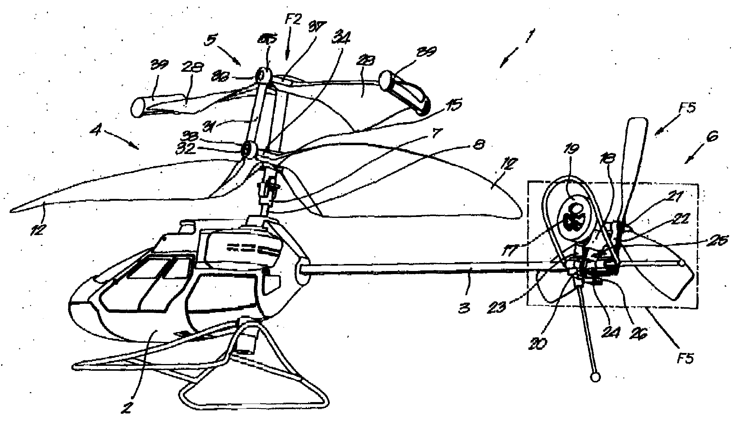
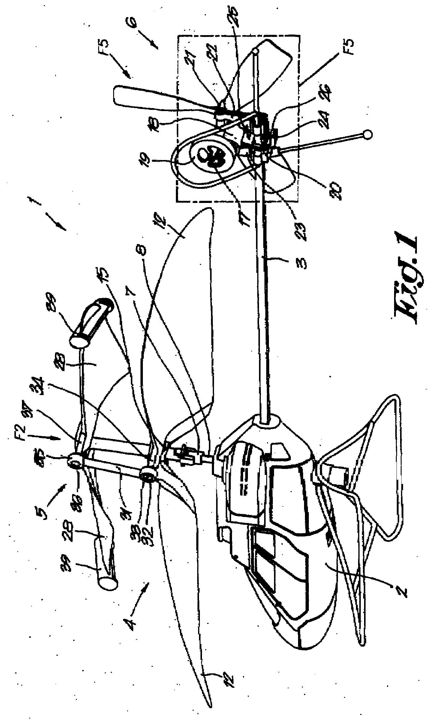
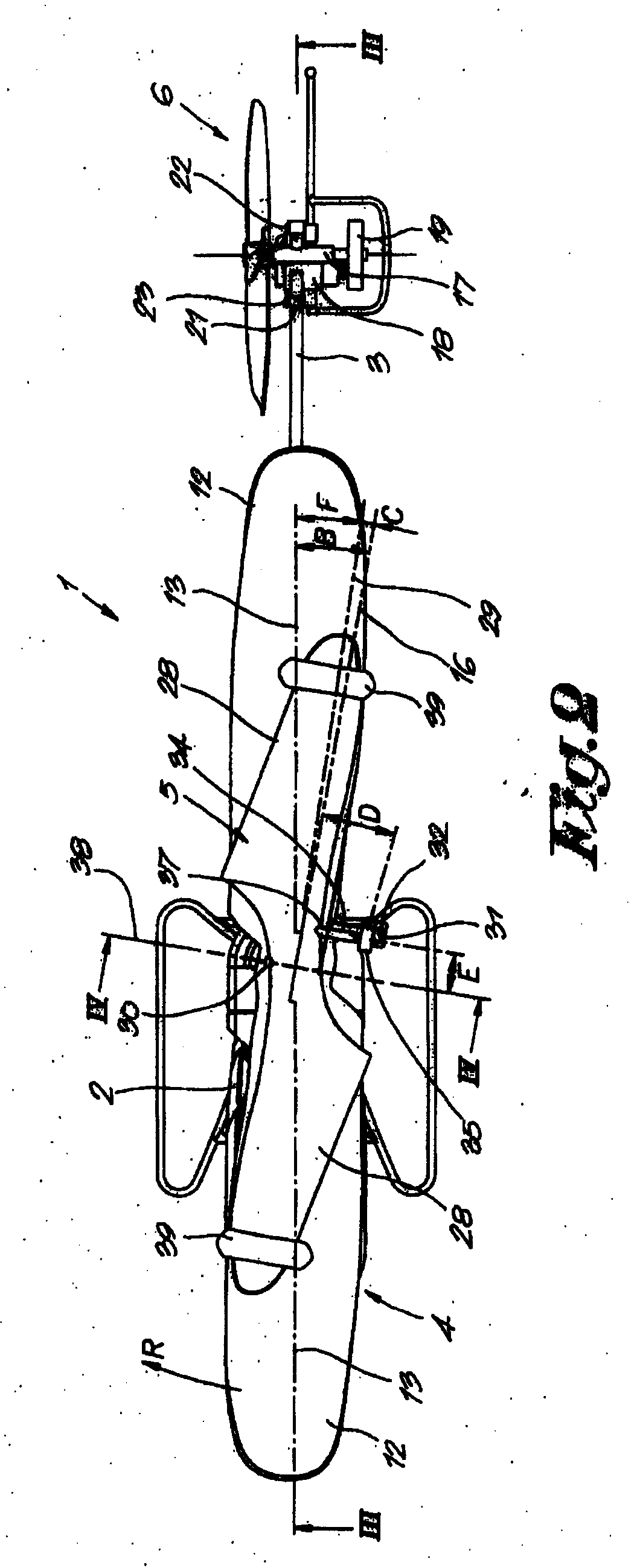
[0053]The helicopter 1 represented in the figures by way of example is a remote-controlled helicopter which essentially consists of a body 2 with a landing gear and a tail 3; a main rotor 4; an auxiliary rotor 5 driven synchronously with the latter and a tail rotor 6.

[0054]The main rotor 4 is provided by means of what is called a rotor head 7 on a first upward directed rotor shaft 8 which is bearing-mounted in the body 2 of the helicopter 1 in a rotating manner and which is driven by means of a motor 9 and a transmission 10, whereby the motor 9 is for example an electric motor which is powered by a battery 11.

[0055]The main rotor 4 in this case has two propeller blades 12 which are in line or practically in line, but which may just as well be composed of a larger number of propeller blades 12.

[0056]The tilt or angle of incidence A of the propeller blades 12, in other words the angle A which forms the propeller blades 12 as represented in FIG. 6 with the plane of rotation 14 of the m...


PUM


Abstract

A helicopter has a main rotor with propeller blades which is driven by a rotor shaft and which is hinge-mounted to this rotor shaft. The angle between the surface of rotation of the main rotor and the rotor shaft may vary. A swinging manner on an oscillatory shaft is essentially transverse to the rotor shaft of the main rotor and is directed transversally to the longitudinal axis of the vanes. The main rotor and the auxiliary rotor are connected to each other by a mechanical link. The swinging motions of the auxiliary rotor controls the angle of incidence (A) of at least one of the propeller blades of the main rotor. There are wings from the body and a stabilizer at the tail.

Description

RELATED APPLICATION[0001]This application is a Continuation-in-Part of U.S. patent application Ser. No. 11 / 462,177, filed on Aug. 3, 2006 and entitled HELICOPTER, which claims priority to Belgian Patent Application No. 2006 / 0043 entitled AUTOSTABIELE HELICOPTER by Alexander VAN DE ROSTYNE, which was filed on Jan. 19, 2006. The contents of these applications are incorporated by reference herein.BACKGROUND[0002]The present disclosure concerns an improved helicopter.[0003]The disclosure concerns a helicopter generally. In particular, but not exclusively, it is related to a toy helicopter and in particular to a remote-controlled model helicopter or a toy helicopter.SUMMARY[0004]It known that a helicopter is a complex machine which is unstable and as a result difficult to control, so that much experience is required to safely operate such helicopters without mishaps.[0005]Typically, a helicopter includes a body, a main rotor and a tail rotor.[0006]The main rotor provides an upward force ...

Claims


Application Information

Patent Timeline
Patent Type & Authority Applications(United States)
IPC IPC(8): B64C27/10
CPCA63H27/12B64C27/467B64C27/54B64C27/473
Inventor VAN DE ROSTYNE, ALEXANDER JOZEF MAGDALENA
Owner SILVERLIT TOYS MANUFACTORY
Learn More