
Method and magnetic resonance apparatus for dynamic magnetic resonance imaging

a magnetic resonance imaging and dynamic magnetic resonance technology, applied in the field of magnetic resonance apparatus for dynamic magnetic resonance imaging, can solve the problems of incomplete acquisition of sub-data sets, and achieve the effects of small reconstruction time, and high temporal and spatial resolution

Inactive Publication Date: 2011-12-06
SIEMENS HEALTHCARE GMBH
View PDF4 Cites 13 Cited by
  • Summary
  • Abstract
  • Description
  • Claims
  • Application Information

AI Technical Summary

Benefits of technology

[0020]An object of the present invention is to provide a method for dynamic MRI that allows a high temporal and spatial resolution, that requires a small reconstruction time and that is robust with regard to artifacts, in particular with regard to movement artifacts and magnetic field inhomogeneities and with regard to an under-sampling of k-space. Furthermore, it is an object of the invention to provide a magnetic resonance apparatus or a computer software product (i.e. a computer-readable medium encoded with a data structure) for dynamic MRI, with a high temporal and spatial resolution with simultaneously lower reconstruction time and robustness with regard to artifacts.
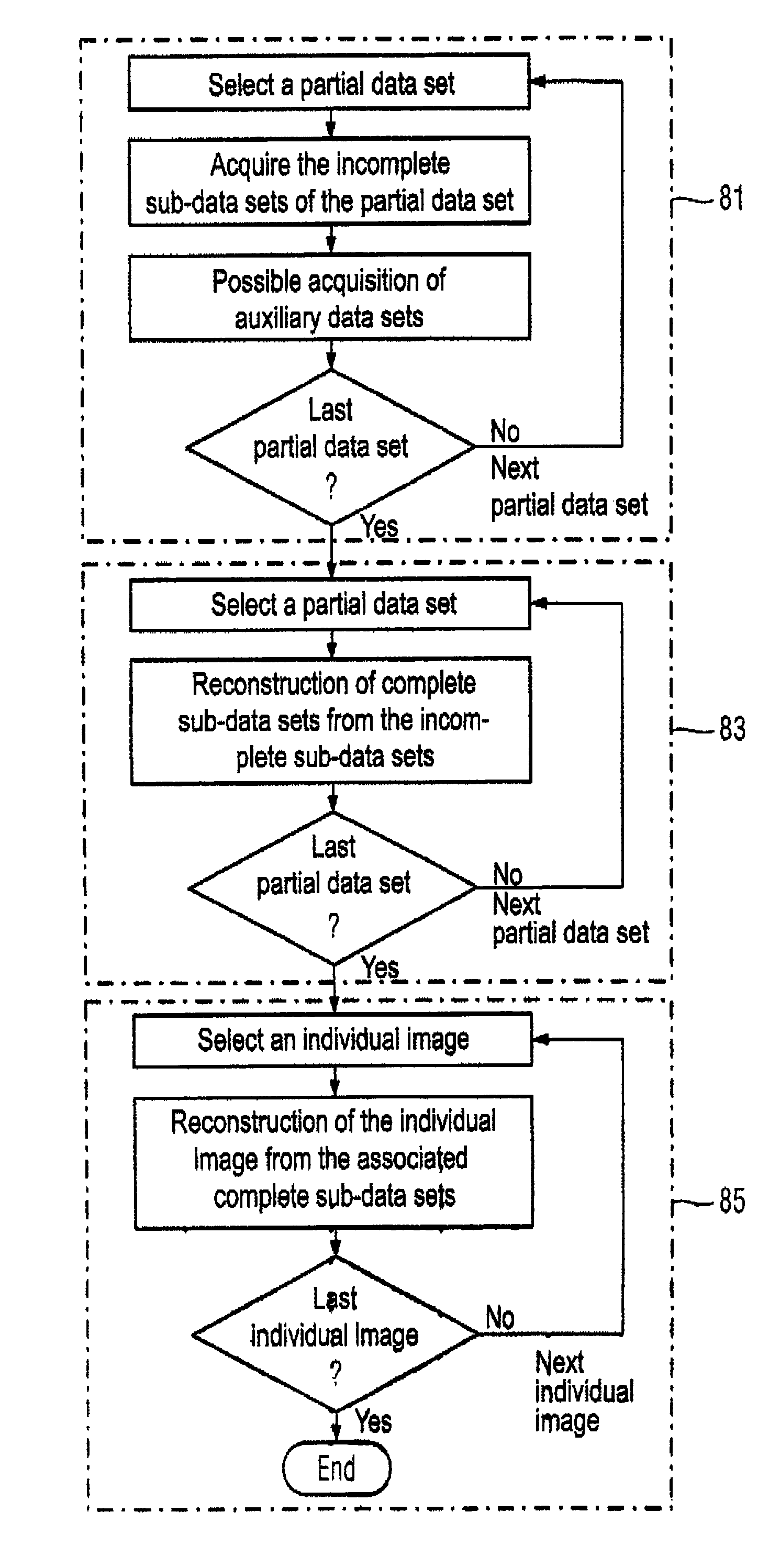
[0027]The incomplete sub-data sets of a partial data set preferably are acquired immediately after one another in succession. This allows the data sets to be acquired while the gradient fields that are activated during the acquisition of the measurement data are as uniform as possible, so as to minimize unwanted effects that would cause artifacts (for example, as a result of eddy currents). In the event that unwanted patient movements occur during the examination (which patient movement is superimposed on the dynamic organ movement), data acquisition in this manner will also generally reduce the number of the corrupted partial data sets.
[0031]In another preferred embodiment, the different sampling schemes used in the acquisition of the incomplete sub-data sets alternate cyclically. Sampling schemes that alternate cyclically generate a periodicity in the acquisition of the incomplete sub-data sets. This allows a simple reconstruction of the complete sub-data sets therefrom.
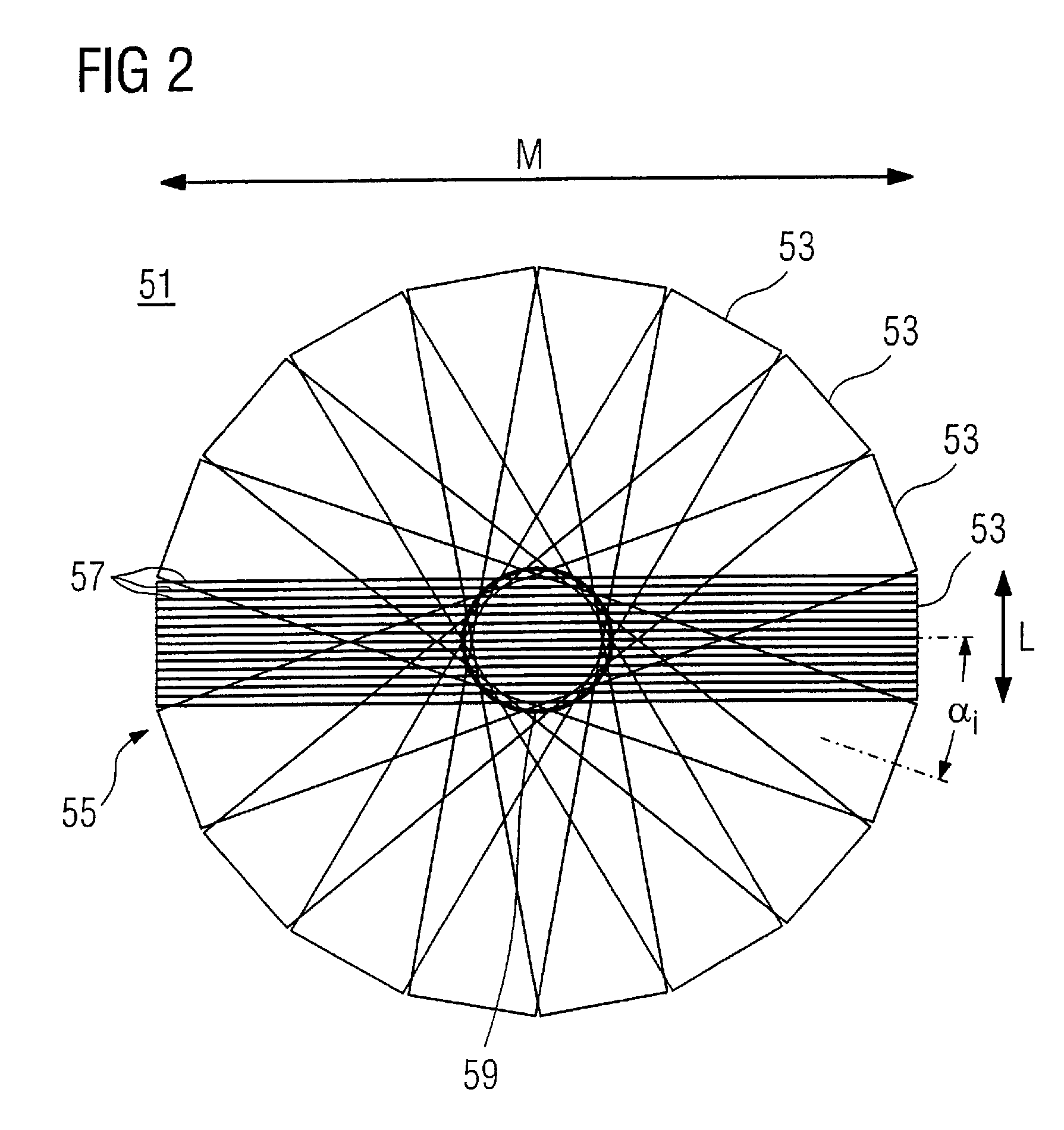
[0032]In an embodiment that can be implemented particularly simply, A different sampling schemes are used that are characterized by only every Ath k-space line of the sampling grid being sampled in each sampling scheme, and the sampled k-space lines are shifted from sampling scheme-to-sampling scheme. The number A is typically a single-digit whole number. The use of such sampling schemes can be realized particularly simply and has the advantage that such sampling schemes allow a particularly simple reconstruction of complete sub-data sets from incomplete sub-data sets.
[0033]The acquisition of the incomplete sub-data sets advantageously ensues with a number of coil elements each with a different spatial sensitivity, and information as to the respective sensitivities of the individual coil elements is used in the reconstruction of the complete sub-data sets from the incomplete sub-data sets. The precision of the reconstruction of complete sub-data sets from incomplete sub-data sets is thereby increased.
[0034]In an embodiment of the method, the reconstruction of the complete sub-data sets from the incomplete sub-data sets is implemented using further complete auxiliary data sets that are associated with a central k-space range. Such auxiliary data sets allow a particularly simple and precise reconstruction of the sub-data sets.

Problems solved by technology

The acquired sub-data sets thus are incomplete, meaning that not all grid points of the k-space segment are occupied by measurement data in the data acquisition procedure.

Method used


Image

  • Method and magnetic resonance apparatus for dynamic magnetic resonance imaging
  • Method and magnetic resonance apparatus for dynamic magnetic resonance imaging
  • Method and magnetic resonance apparatus for dynamic magnetic resonance imaging

Examples


Embodiment Construction

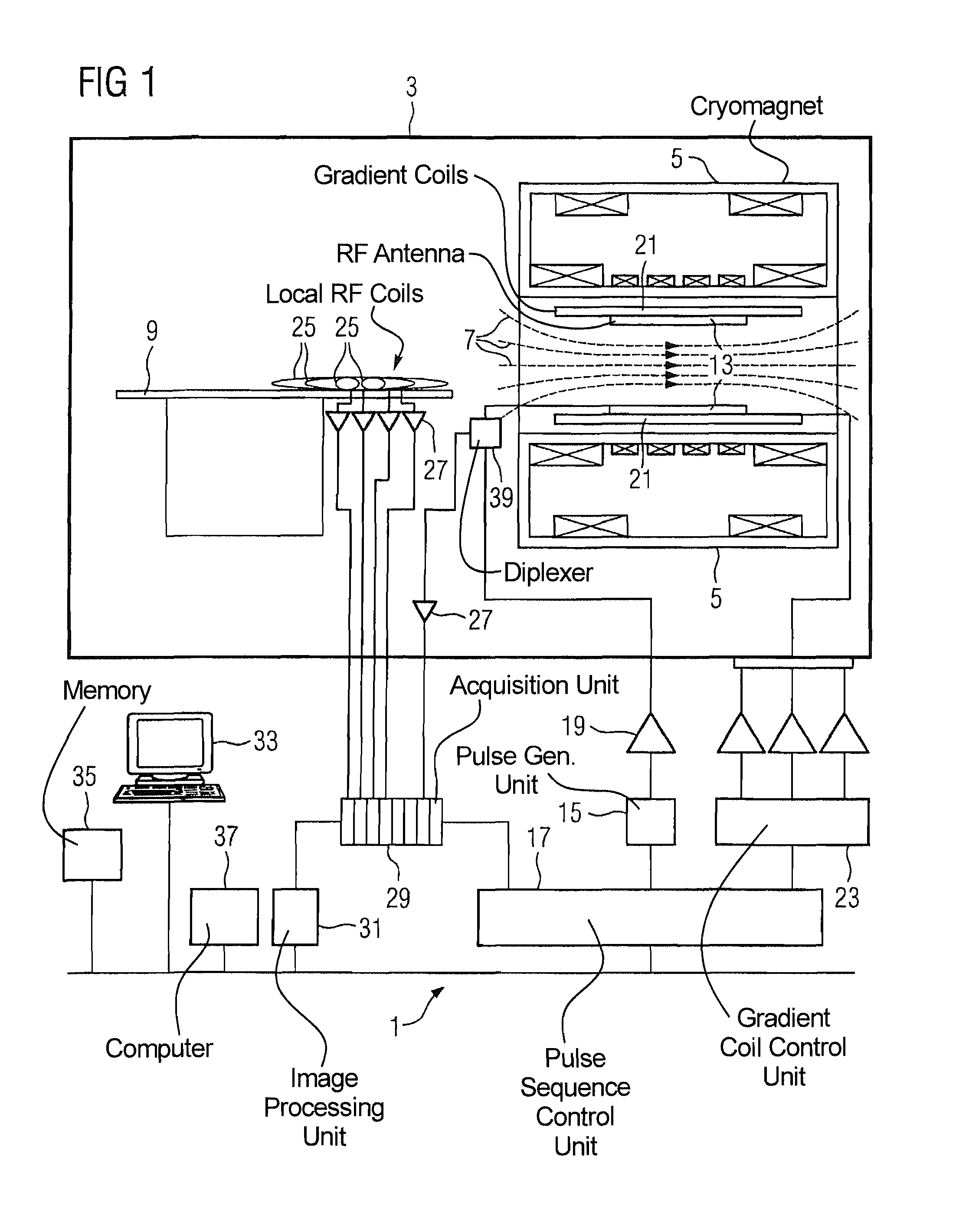
[0045]FIG. 1 schematically shows the basic design of a magnetic resonance apparatus 1. The components of the magnetic resonance apparatus 1 with which the actual measurement is implemented are located in a radio-frequency-shielded measurement chamber 3. In order to examine the body of a subject by means of magnetic resonance imaging, various magnetic fields tuned precisely to one another in terms of their temporal and spatial characteristics are radiated at the body.

[0046]A strong magnet, typically a cryomagnet 5 with a tunnel-shaped opening, generates a strong, static basic magnetic field 7 that typically amounts to 0.2 Tesla to 3 Tesla and more, and that is substantially homogeneous within a measurement volume. A body to be examined (not shown) is placed on a patient bed 9 and is positioned in the basic magnetic field 7, more precisely in the measurement volume.

[0047]The excitation of nuclear spins in the body ensues by radio-frequency electromagnetic excitation pulses that are ra...


PUM


Abstract

The invention concerns a method and magnetic resonance apparatus for acquisition and generation of a time-resolved image series of an anatomical organ with a quasi-periodical movement in a subject, k-space is sampled in segments with a number of partial data sets, with the sampling points of each partial data set corresponding to grid points of a Cartesian sampling grid of a k-space segment, and the Cartesian sampling grids of the k-space segments being rotated relative to one another. A series of sub-data sets is incompletely acquired for each partial data set using alternating sampling schemes. Each incomplete sub-data set is associated with one of the individual images. For at least some of the partial data sets, complete sub-data sets are reconstructed from the incomplete sub-data sets. For the reconstruction of the individual images, in each of the individual images, at least some of the complete sub-data sets that are associated with this individual image are used.

Description

BACKGROUND OF THE INVENTION[0001]1. Field of the Invention[0002]The present invention concerns a method for acquisition and generation of a time-resolved image series by means of magnetic resonance technology, as is particularly suitable in the context of medical examinations for representation of the movement cycle of an anatomical organ with a quasi-periodic movement.[0003]2. Description of the Prior Art[0004]Magnetic resonance imaging is a medical imaging modality that has been successfully established for years. Described with significant simplification, magnetic fields of different strengths and spatial and temporal characteristics hereby induce nuclear magnetic resonances in a subject to be examined that cause detectable signals to be emitted. The detected measurement data are typically arranged in a two-dimensional or three-dimensional mathematical space or domain (known as k-space) that is related with the image space or domain via a Fourier transformation.[0005]In recent ti...

Claims


Application Information

Patent Timeline
Patent Type & Authority Patents(United States)
IPC IPC(8): A61B5/055
CPCG01R33/4824G01R33/5611G01R33/5614G01R33/56325G01R33/5673
Inventor STEMMER, ALTO
Owner SIEMENS HEALTHCARE GMBH
Learn More