Photosensitive optical fiber for a bragg grating filter, a method of fabricating said fiber, and a chromatic dispersion and chromatic dispersion slope compensator including a fiber of this kind

Inactive Publication Date: 2002-06-04
II VI DELAWARE INC
View PDF11 Cites 14 Cited by
  • Summary
  • Abstract
  • Description
  • Claims
  • Application Information

AI Technical Summary

Benefits of technology

To this end, the invention proposes a photosensitive optical fiber for forming an optically induced Bragg grating filter, said optical fiber having a core and a cladding, said core of said fiber having a refractive index n.sub.c and said cladding of said fiber having a refractive index n.sub.g, said core being doped with a photosensitive first element, and said first element being Germanium, wherein the concentration C.sub.Ge of Ge in the core is at least equal to 10%: C.sub.Ge.gtoreq.10%, and wherein said core is further doped with a photosensitive or non-photosensitive second element to reduce the refractive index n.sub.c of the core to reduce the refractive index difference to a value less than: .DELTA.n=n.sub.c -n.sub.g.ltoreq.6.times.10.sup.-3. This low refractive index step is to minimize the unwanted effect of PMD.

Problems solved by technology

The risk of errors at the receiver due to this widening is lower if the pulses are sufficiently spaced in time.
However, in very high bit rate systems the temporal widening can be comparable with the spacing between pulses, leading to the possibility of an error rate unacceptable to the link operator.
However, the method taught by document D1 is difficult to implement and would seem to be ill-suited to an industrial scale process.
Uncontrolled effects such as fluctuations of the fiber and mechanical vibrations cause quasi-interferometric noise.
However, technical process control problems arise in implementing devices having a greater usable bandwidth: aligning and focusing the laser onto the core of the fiber, controlling the acceleration and rate of displacement of the fiber, etc.

Method used


Image

  • Photosensitive optical fiber for a bragg grating filter, a method of fabricating said fiber, and a chromatic dispersion and chromatic dispersion slope compensator including a fiber of this kind
  • Photosensitive optical fiber for a bragg grating filter, a method of fabricating said fiber, and a chromatic dispersion and chromatic dispersion slope compensator including a fiber of this kind
  • Photosensitive optical fiber for a bragg grating filter, a method of fabricating said fiber, and a chromatic dispersion and chromatic dispersion slope compensator including a fiber of this kind

Examples


Embodiment Construction

In all the figures, the same reference symbols designate the same components, but for clarity not all the figures are to the same scale.

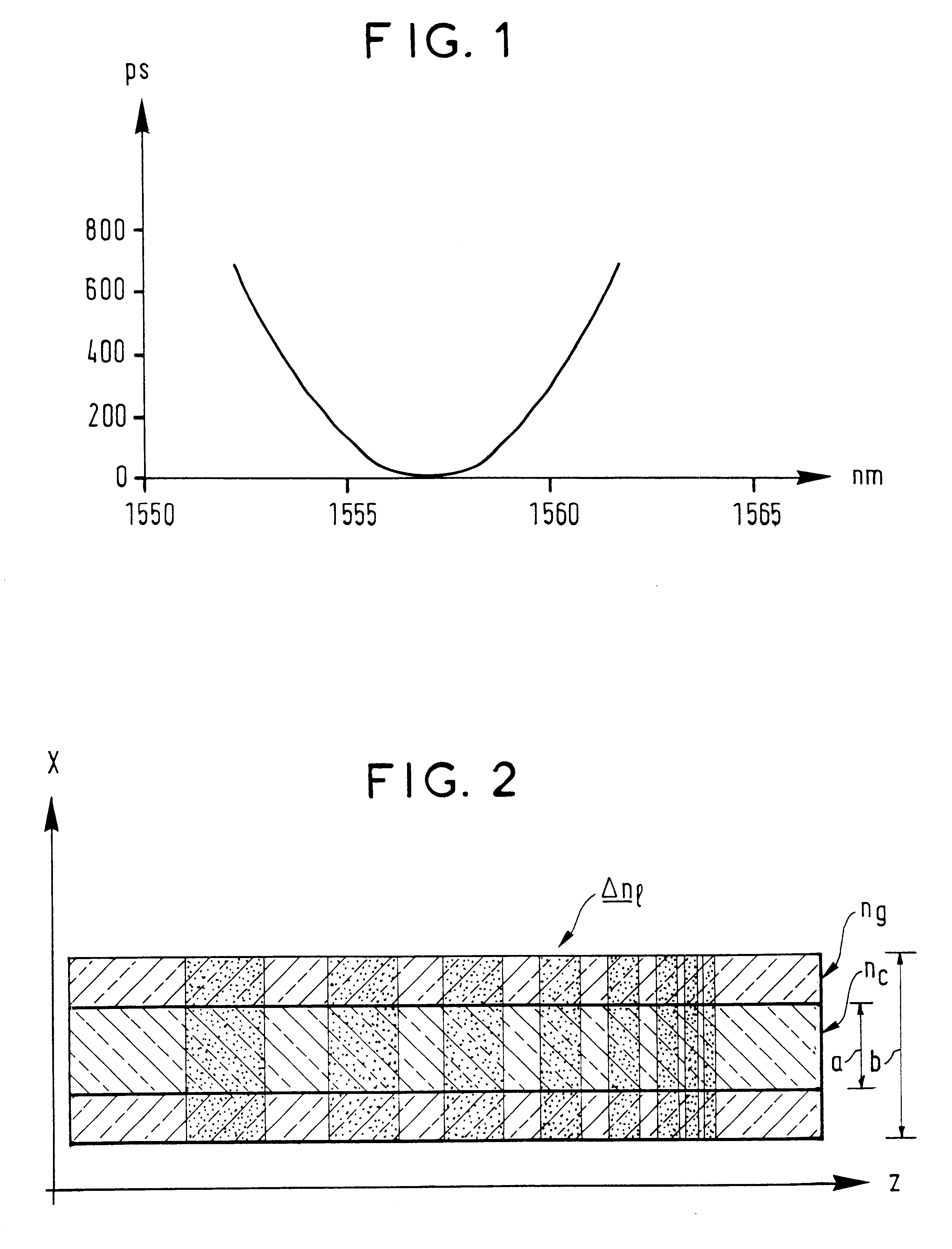
FIG. 1 shows an example of chromatic dispersion to be corrected, as might be observed in a repeater in a very long haul optical link. A link of this kind is typically made up of a plurality of sections of optical fiber which connect a plurality of stations or repeaters in which the signals to be propagated are periodically amplified and reshaped before they are transmitted in another section. As is clear from the documents cited above, the use of Bragg grating filters to correct chromatic dispersion and even chromatic dispersion slope is well-known. If the correction is successful, the variation of the group time with wavelength shown in FIG. 1 is canceled out, i.e. the group time is the same for all wavelengths in the wanted transmission band.

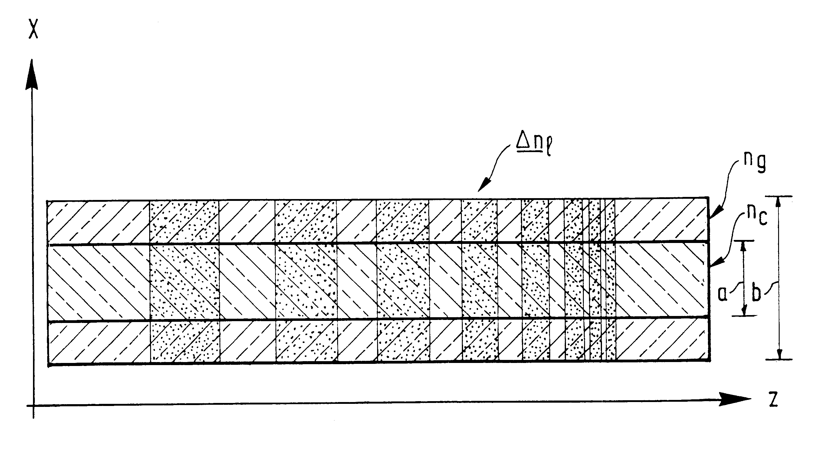
FIG. 2 is a diagram showing an example of an optical fiber in accordance with a feature of the invention ha...


PUM


Abstract

The invention proposes a photosensitive optical fiber for inscribing a Bragg grating by UV illumination, in which the photosensitivity is very high either to reduce the exposure time or to increase the contrast of the optically induced refraction index variations, whilst retaining a reasonable exposure time. Thanks to this high contrast, the fiber of the invention, imprinted with a linear chirp, in addition to correcting chromatic dispersion, is also effective in correcting the chromatic dispersion slope of a fiber of ordinary contrast, imprinted with a quadratic chirp. In a preferred embodiment, the fiber of the invention is photosensitive in the cladding. In a particularly advantageous embodiment, a non-photosensitive dopant is added to the core of said fiber to reduce the refractive index in the core, reducing the birefringence of the fiber.

Description

The field of the invention is that of fiber optic telecommunications. The invention relates to a photosensitive fiber for fabricating a Bragg grating filter and to a method of fabricating a fiber of this kind. The filter obtained using this fiber is particularly suitable for compensating chromatic dispersion and chromatic dispersion slope effects in a fiber optic link without introducing any penalty in terms of polarization mode dispersion.The effects of chromatic dispersion are cumulative over the length of the link and are therefore greater on long links. Also, chromatic dispersion causes temporal widening of the pulses transmitted over the link. The risk of errors at the receiver due to this widening is lower if the pulses are sufficiently spaced in time. However, in very high bit rate systems the temporal widening can be comparable with the spacing between pulses, leading to the possibility of an error rate unacceptable to the link operator.In a practical link, as deployed at pr...

Claims


Application Information

Patent Timeline
IPC IPC(8): G02B6/34G02B6/00G02B5/18G02B6/02
CPCG02B6/02085G02B6/02114G02B6/02109
Inventor RIANT, ISABELLESANSONETTI, PIERRE
Owner II VI DELAWARE INC
Why Eureka
Try Eureka