
Variable stop collimator

a collimator and variable stop technology, applied in the field of collimators, can solve the problems of long treatment time and may be expensive for patients

Inactive Publication Date: 2007-07-19
NORTH AMERICAN SCI
View PDF8 Cites 28 Cited by
  • Summary
  • Abstract
  • Description
  • Claims
  • Application Information

AI Technical Summary

Problems solved by technology

Devices incorporating such an open and shut configuration require time for the leaves to implement these motions, thus resulting in longer treatment times which may be expensive for the patient and uncomfortable since the patient must remain in an immobilized state.

Method used


Image

  • Variable stop collimator
  • Variable stop collimator
  • Variable stop collimator

Examples


Embodiment Construction

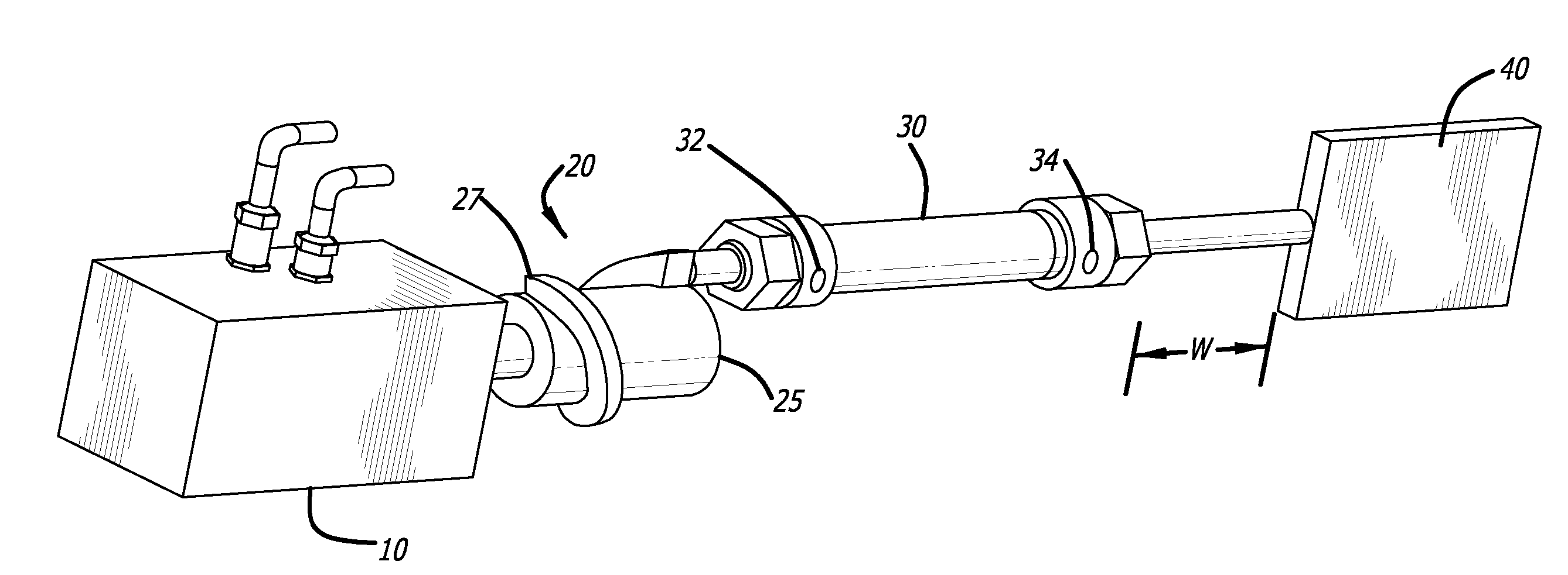
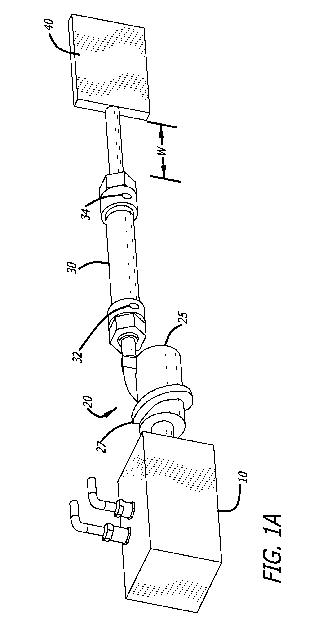
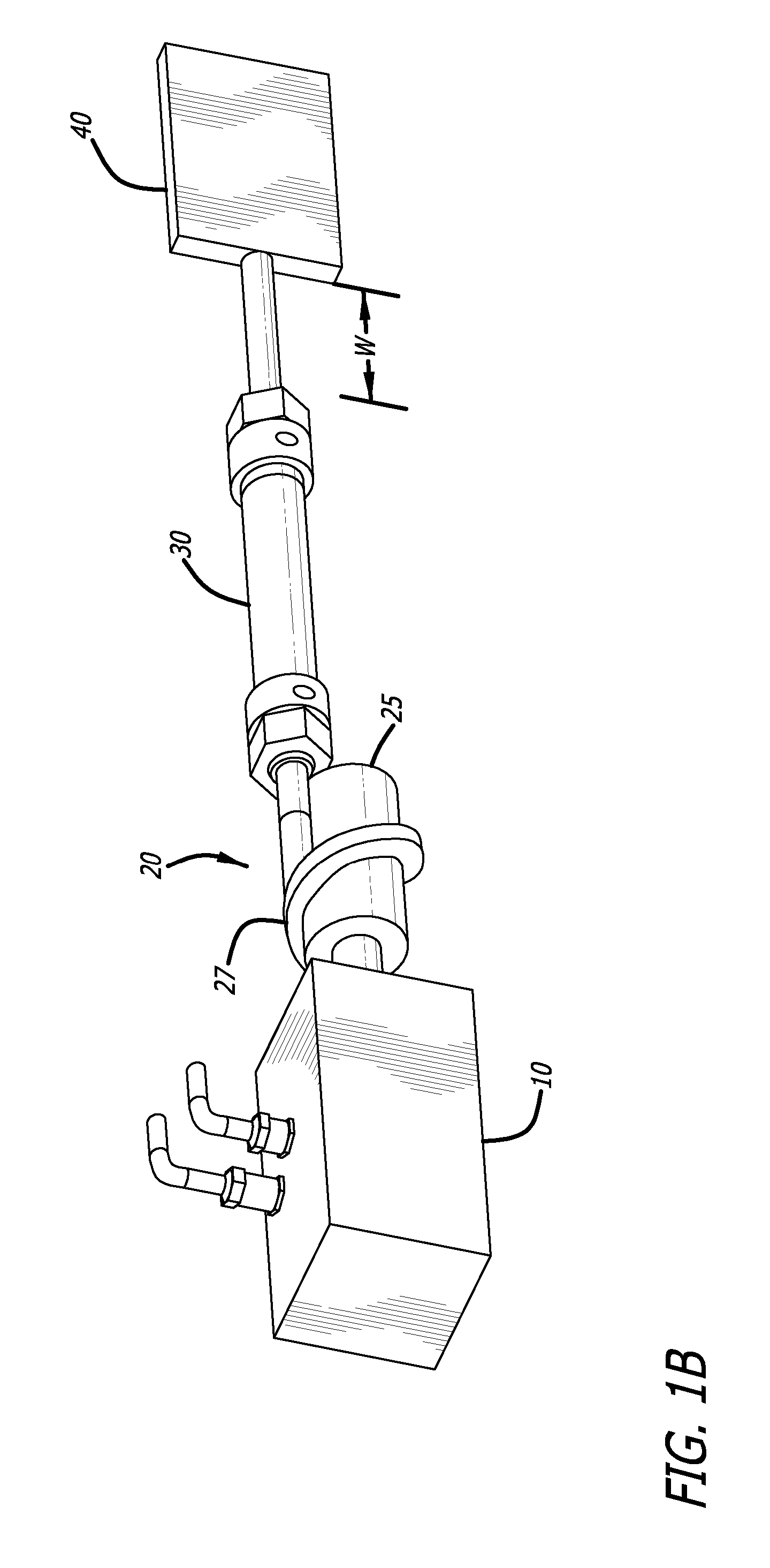
[0023] The present disclosure is directed to a variable stop collimator. The collimator incorporates a motor having a spiral stop positioned on the motor's shaft. The spiral stop mechanically controls the positioning of a pneumatic cylinder used to drive a leaf of the collimator. The leaves may be either fully or partially open to permit a radiation beam or its beam plane to pass therethrough. The collimator permits a precise beam to be defined, while also allowing--via one or more motion sensors--for adjustment of this precise beam to account for the patient's breathing.

[0024] Referring now to FIG. 1A, illustrated is a collimator having a leaf in its fully closed position in accordance with one embodiment of the present disclosure. The collimator may include twenty (20) to forty (40) of the combination of elements shown in FIG. 1A. The combination includes a motor 10, the shaft of which is coupled to substantially the central axis of a variable stop 20. It should be noted that the...


PUM


Abstract

A variable stop collimator for use in a radiation therapy machine having a radiation source for producing a radiation beam directed toward a patient. The variable stop collimator includes a plurality of radiation attenuating leaves, with each leaf having an opposing leaf to collimate a ray of the radiation beam. For each leaf, the collimator includes a pneumatic cylinder configured to independently move each leaf between the open and closed state and at points between the open and closed states. Each pneumatic cylinder is connected at one end to the leaf and, at the other end, to a variable stop. The stop may include a raised spiral projection that permits a smooth stop at any point deemed appropriate for the motor. The collimator includes a support configured to guide the plurality of radiation attenuating leaves transverse to the beam plane.

Description

BACKGROUND [0001] 1. Field [0002] The present disclosure relates to radiation treatment for tumors and, more particularly, to a collimator that more precisely focuses a radiation source via partially opening a radiation attenuating leaf. [0003] 2. Description of Related Art [0004] Radiation therapy is a common treatment option for patients with tumors. Collimators are commonly used to define a radiation beam used to irradiate tumors. Because radiation therapy is focused on treating the tumor and not destroying healthy tissue, it is highly desirable that the radiation beam is focused to define an exact point of radiation and with a high degree of accuracy. A significant number of tumors tend to have irregular contours. Collimators have been used to assist in defining exact points of radiation for such irregularly defined tumors, as well as tumors having more conventionally-recognized shapes. [0005] A very important aspect of a collimator is its leaves. With some of today's collimator...

Claims


Application Information

Patent Timeline
Patent Type & Authority Applications(United States)
IPC IPC(8): G21K1/04
CPCG21K1/046G21K1/04
Inventor TERWILLIGER, RICK A.CUTRER, L. MICHAEL
Owner NORTH AMERICAN SCI
Learn More