Antenna radiation collimator structure

Active Publication Date: 2007-07-19
THE GOVERNMENT OF THE US SEC THE AIR FORCE
View PDF3 Cites 137 Cited by
  • Summary
  • Abstract
  • Description
  • Claims
  • Application Information

AI Technical Summary

Benefits of technology

[0008] In another aspect of the present invention, set forth is an antenna beam steering structure. The antenna beam steering structure includes a number of circuit boards interleaved with a number of dielectric sheet spacers to substantially form a block structure. An array of resonator cells may be disposed on top planar surfaces of each of the number of circuit boards and a number of conductive strip lines may be disposed on bottom planar surfaces of each of the number of circuit boards. A metallic sheet may be disposed on a rear facing surface of the block structure, which is adapted to reflect radiation towards a front fac

Problems solved by technology

In order to provide a bidirectional beam, the convergent lenses, angular filters or guided wave horns would have to be used in pairs, which may contribute to system costs.
Furthermore, there can be a significant loss in signal or beam intensity when using convergent lenses or angular filters to convert from the omni-directio

Method used


Image

  • Antenna radiation collimator structure
  • Antenna radiation collimator structure
  • Antenna radiation collimator structure

Examples


Embodiment Construction

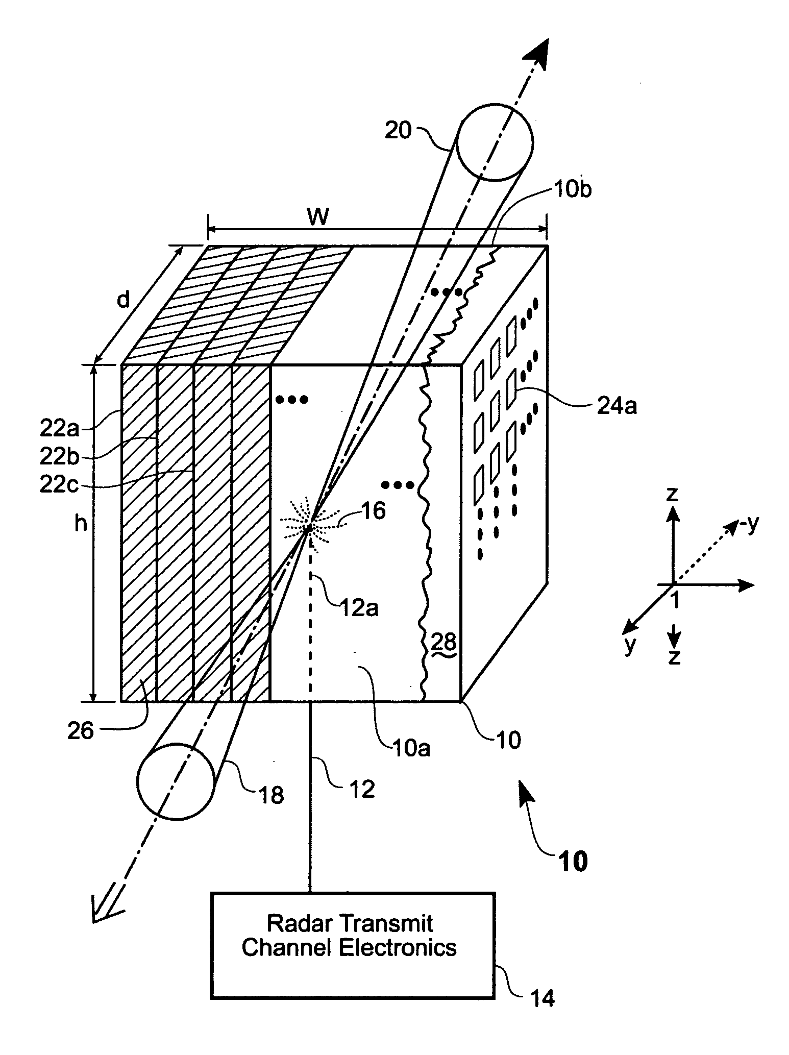
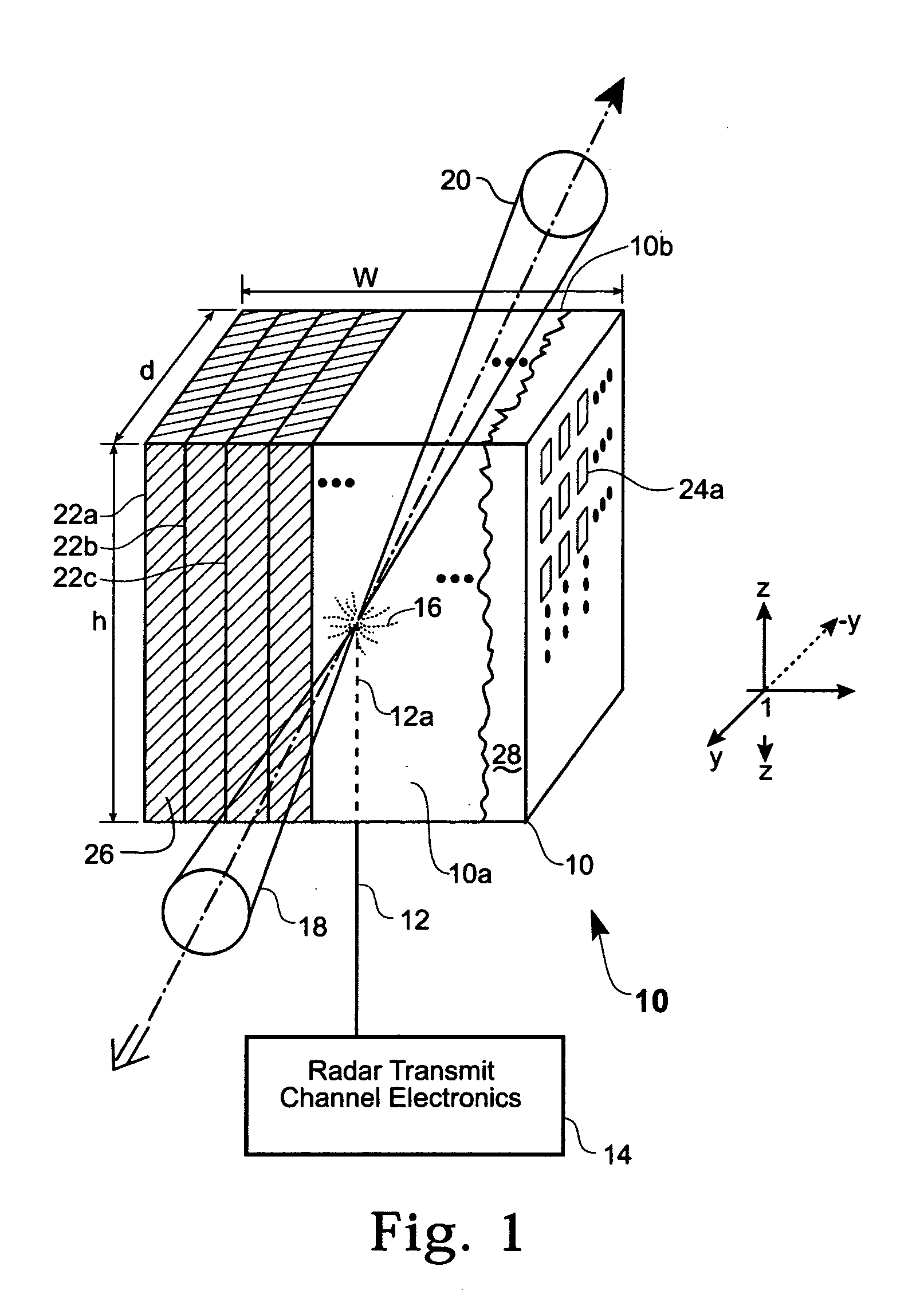
[0018] The present invention provides an antenna radiation collimator structure. The antenna radiation collimator structure is constructed and arranged for redirecting incident omni-directional radiation, which is transmitted by an antenna, into first and second collimated radiation beams that include a relatively greater beam intensity than the originally transmitted omni-directional radiation. The antenna radiation collimator structure may be employed in a number of applications including applications that require a collimated radiation beam having increased beam intensity or power without increasing the output power or radiation transmission of the antenna. As will be described in further detail below, suffice it to say here, the antenna radiation collimator structure provides a lightweight, compact structure that can be mounted on a conventional omni-directional transmission antenna for converting omni-directional radiation emitted from the antenna into one or more collimated be...


PUM


Abstract

An antenna radiation collimator structure is provided as including a number of resonator circuit boards oriented to form a block structure. A sheet of dielectric material is disposed between each of the number of resonator circuit boards to maintain a substantially uniform spacing between each of the resonator circuit boards. A plurality of conductive unit resonator cells may be disposed on first planar surfaces of each of the number of resonator circuit boards and a plurality of conductive strip lines may also be disposed on second planar surfaces of each of the number of resonator circuit boards. In this arrangement, radiation applied to a substantially central location of the block structure interacts with the plurality of conductive unit resonator cells and the plurality of conductive strip lines for redirecting the radiation out of front and rear facing surfaces of the block structure as respective first and second substantially collimated beams.

Description

STATEMENT OF GOVERNMENT INTEREST [0001] The invention described herein may be manufactured and used by or for the Government for governmental purposes without the payment of any royalty thereon. FIELD OF THE INVENTION [0002] The present invention relates generally to antennas and, more particularly, to an antenna structure adapted for transmitting a collimated electromagnetic beam having predetermined beam width. BACKGROUND OF THE INVENTION [0003] As is known, conventional physically narrow antennas, such as balanced sleeve dipole antennas, transmit omni-directional electromagnetic radiation with substantially uniform intensity in all directions. It is often desirable, however, to focus or provide a collimated radiation beam to a particular target, such as in radar target acquisition and / or searching operations. Conventional structures for receiving and converting the omni-directional radiation beam to a collimated radiation beam generally include convergent lenses, angular filters ...

Claims


Application Information

Patent Timeline
IPC IPC(8): H01Q1/38
CPCH01Q1/38H01Q15/0086H01Q25/005H01Q15/10
Inventor TURCHINETZ, BEVERLYDEROV, JOHNCRISMAN, EVERETT
Owner THE GOVERNMENT OF THE US SEC THE AIR FORCE
Why Eureka
Try Eureka