Planar light source unit and image display apparatus using the same

a technology of image display and light source unit, which is applied in the direction of lighting and heating apparatus, instruments, transportation and packaging, etc., can solve the problems of insufficient strength and reliability, mechanical fastening method, and difficulty in keeping the mechanical strength of liquid crystal display device, so as to enhance mechanical reliability and reduce the distortion of the resin frame

Inactive Publication Date: 2007-07-19
TRIVALE TECH
View PDF6 Cites 45 Cited by
  • Summary
  • Abstract
  • Description
  • Claims
  • Application Information

AI Technical Summary

Benefits of technology

[0010]In view of the above circumstances of the above planar light source unit, it is an object of the invention to provide a planar light source unit which can reduce the distortion of a resin frame caused by temperature to thereby enhance the mechanical reliability thereof, and an image display apparatus using such planar light source unit.

Problems solved by technology

Recently, as the display screen of the liquid crystal display device increases, the frame of the case tends to become further narrower, which makes it difficult to keep the mechanical strength of the liquid crystal display device.
However, when holding the following parts of the planar light source unit between the upper and lower cases, that is, a light guide plate, an optical sheet and a resin frame having not only a function to reflect the light emitted from the side surface of the light guide plate again onto the light guide plate but also a screwing and mounting function to connect the planar light source unit to an external case, the mechanical fastening method as disclosed in JP-A-11-143383 is not able to provide sufficient strength and reliability.
Such distortion, when it becomes large, has a mechanical influence on the reflecting sheet and light guide plate, which gives rise to variations in the luminance of the planar light source unit at high temperatures.

Method used


Image

  • Planar light source unit and image display apparatus using the same
  • Planar light source unit and image display apparatus using the same
  • Planar light source unit and image display apparatus using the same

Examples


embodiment 1

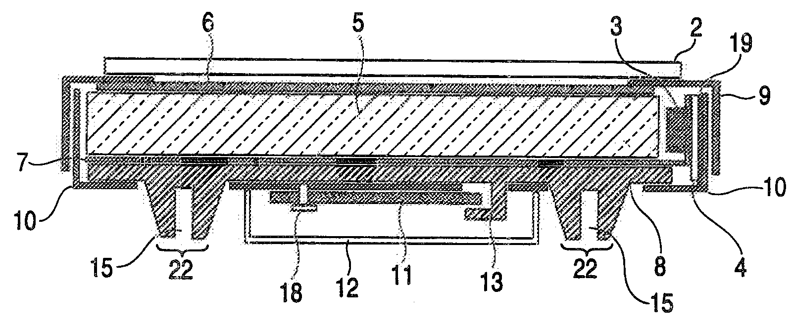
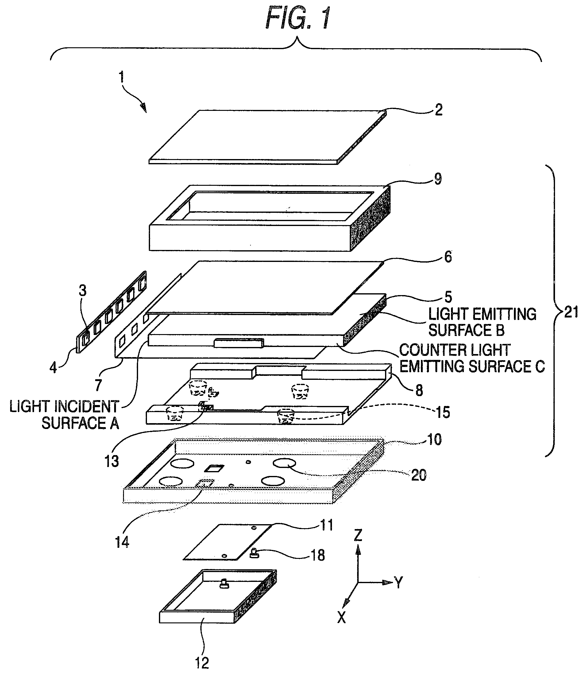
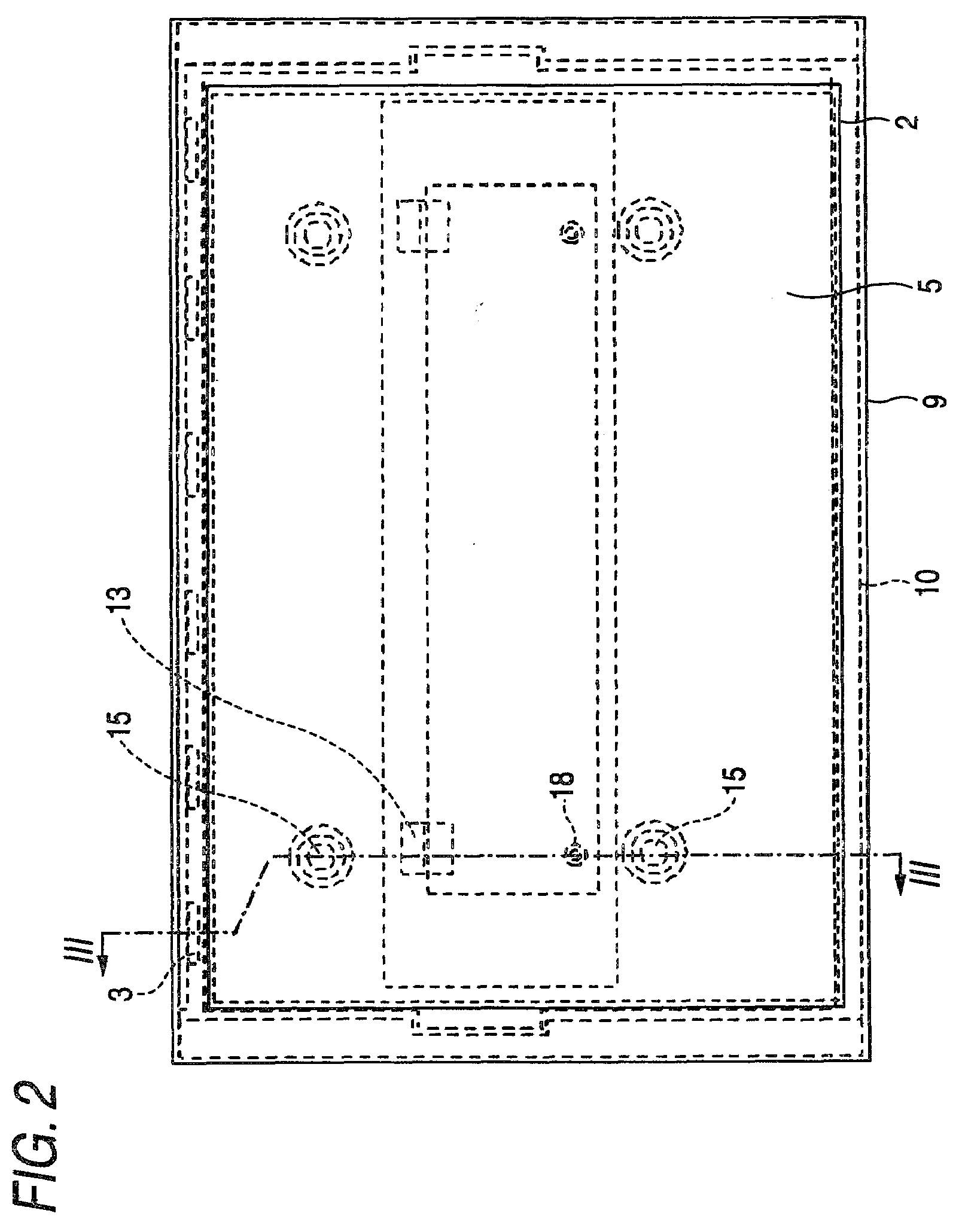
[0020]FIG. 1 shows an exploded perspective view of a liquid crystal display apparatus 1 according to the present embodiment, and FIG. 2 shows a plan view (a conceptual view) thereof, respectively. The liquid crystal display apparatus 1 shown in FIG. 1 includes a liquid crystal display part 2 and a planar light source unit 21; and, within the planar light source unit 21, there are arranged two or more LEDs 3 in a line, while the LEDs 3 are respectively connected to a light source substrate 4. Also, the LEDs 3 are disposed in the vicinity of one side surface (the side surface through which the light from a light source enters is hereinafter referred to as a light incident surface A) of a light guide plate 5, while the light having entered the light guide plate 5 through the light incident surface A is emitted from the light emitting surface B of the light guide plate 5. (Here, the light emitting surface is the plane of the light guide plate which faces the liquid crystal display part ...

embodiment 2

[0059]FIG. 4 is a section view of a liquid crystal display apparatus according to an embodiment 2 of the invention. The liquid crystal display apparatus according to the present embodiment, a protection case 12 (a second member) for a circuit board 11 (a first member) is mounted onto a lower case 10. Therefore, with regard to its assembling method and structure, up to the step of mounting the circuit board 11 to the lower case 10, the present embodiment is basically similar to the above-mentioned embodiment 1 and thus, in order to avoid duplicate and redundant description, the detailed description thereof is omitted here.

[0060]According to the present embodiment, on the resin frame 8, besides the L-shaped pawls A (13) for fixing a circuit board, there is provided another L-shaped pawl B (16) (a fixing member) for fixing the protection case 12. Also, in the side surface of the protection case 12, there is formed an L-shaped pawl B hole 17 into which the L-shaped pawl B (16) of the re...

embodiment 3

[0064]FIG. 5 shows a section view of a liquid crystal display apparatus according to an embodiment 3 of the invention. The liquid crystal display apparatus according to this embodiment includes a groove in the side surface of a projecting portion 30 (a first restriction member) that is extended substantially perpendicularly from the counter light emitting surface side of the resin frame 8, and a groove in the side surface of the projecting portion 32, instead of the L-shaped pawl-like members such as the L-shaped pawl A (13) and L-shaped pawl B (16) respectively provided in the above-mentioned embodiments 1 and 2. By inserting the circuit board 11 and protection case 12 into these grooves, the circuit board 11 and protection case12 are fastened to the resin frame 8. The assembling methods and structures of other composing members are similar to the above-mentioned embodiment 1 and thus, in order to avoid duplicate and redundant description, the detailed description thereof is omitte...


PUM

PropertyMeasurementUnit
reflectanceaaaaaaaaaa
heat expansion coefficientaaaaaaaaaa
temperatureaaaaaaaaaa

Abstract

A planar light source unit includes: a light source; an upper case having an opening through which the light is emitted from the light source; a lower case fitted with the upper case and including a hole; a light guide plate disposed inside the upper case and the lower case; a resin frame including a first surface that holds the light guide plate, a second surface opposed to the first surface, a first restriction member penetrated through the hole of the lower case, the first restriction member including a first portion extending from and substantially perpendicular to the second surface, and a second portion contacted with a portion of the first portion and having a third surface substantially parallel to the second surface; and a first member, a part of which is inserted into a clearance defined by the second surface, the first portion and the third surface.

Description

BACKGROUND OF THE INVENTION[0001]1. Field of the Invention[0002]The present invention relates to a planar light source unit and an image display apparatus using such planar light source unit and, specifically, the invention relates to a planar light source unit including a mechanical fastening method for fastening together a resign frame and a lower case without increasing the number of parts, the method being highly reliable in a wide temperature range, and an image display apparatus using the planar light source unit.[0003]2. Description of the Related Art[0004]A liquid crystal display device, a signboard, a guide light and the like are not a display device of a self-light-emission type that the image display part thereof itself emits the light. In these display devices of a non-self-light-emission type, it is necessary to mount a planar light source unit such as a back light on the counter-light-emission side (the rear surface) of the image display part. Now, description will be ...

Claims


Application Information

Patent Timeline
Patent Type & Authority Applications(United States)
IPC IPC(8): F21V7/04
CPCG02B6/0043G02B6/0055G02F1/133615G02B6/0088G02B6/0068B60R9/04B29C45/00F16B17/00B60R2011/004B60R2011/0061B60Y2304/05
Inventor SAKAI, SEIJI
Owner TRIVALE TECH
Why Eureka
Try Eureka