Eureka AIR delivers breakthrough ideas for toughest innovation challenges, trusted by R&D personnel around the world.

Device for compressing concrete during the manufacture of concrete parts

Inactive Publication Date: 2007-07-19
WACKER NEUSON SE
View PDF1 Cites 0 Cited by
  • Summary
  • Abstract
  • Description
  • Claims
  • Application Information

AI Technical Summary

Benefits of technology

[0014] In general, the bearing structures in such devices for compressing concrete are flexible with respect to the vibration frequency of the vibration exciter. It has turned out that despite the use of the vibration decoupling device (e.g. using spring elements or a layer of foam) to decouple the excited formwork, the bearing structure is excited to vibrations when it has resonant frequencies (resonant frequencies) that are in the area of the excitation frequency of the vibration exciter. This results in undesired noise emissions. Due to the fact that an effort is made to separate the excitation frequency of the vibration exciter and the resonant frequency of the system made up of the bearing structure and the vibration decoupling device, such an interaction effect can be avoided.
[0019] In order to provide the bearing structure with a correspondingly large mass, it is particularly advantageous if the bearing structure is essentially formed by a concrete base. Concrete is not only heavy, but is also relatively economical in relation to its mass. It is thus easily possible to provide the bearing structure with sufficient mass.
[0020] In a particularly advantageous embodiment of the present invention, the bearing structure is decoupled from the ground that supports it in terms of vibration. For example, a soft intermediate layer can be provided between the bearing structure and the floor. In this way, it is possible to decouple the bearing structure from the surrounding building structures, e.g. the floor, the walls, and the foundation. This enables an additional noise reduction.
[0023] While in the prior art, e.g. in the device known from DE 196 31 516 A1, the formwork device in the form of a viscoelastic intermediate layer, is merely inserted between the formwork device (formwork shell) and the bearing structure, in the module according to the present invention the vibration decoupling device is fastened to the formwork device. In this way, it is possible to pre-assemble the entire module at the manufacturing works; i.e., it is possible in particular also to fasten the vibration exciter, in addition to the vibration decoupling device, to the formwork device. In this way, the expense of the final assembly in the concrete part manufacturing works can be significantly reduced.
[0028] The module according to the present invention can thus be assembled, including the electrical equipment, completely in the manufacturing works. At the recipient, i.e. in the concrete part manufacturing works, the module need then merely be placed on a bearing structure present there, e.g. a concrete base. The single electrical connection operation then takes place on location, in that the central plug connector is connected to the supply network by simply plugging it into a socket. The module according to the present invention thus enables what is known as a “plug-and-play” solution, by which the recipient's assembly costs on location can be significantly reduced.

Problems solved by technology

This results in undesired noise emissions.

Method used


Image

  • Device for compressing concrete during the manufacture of concrete parts
  • Device for compressing concrete during the manufacture of concrete parts

Examples


Embodiment Construction

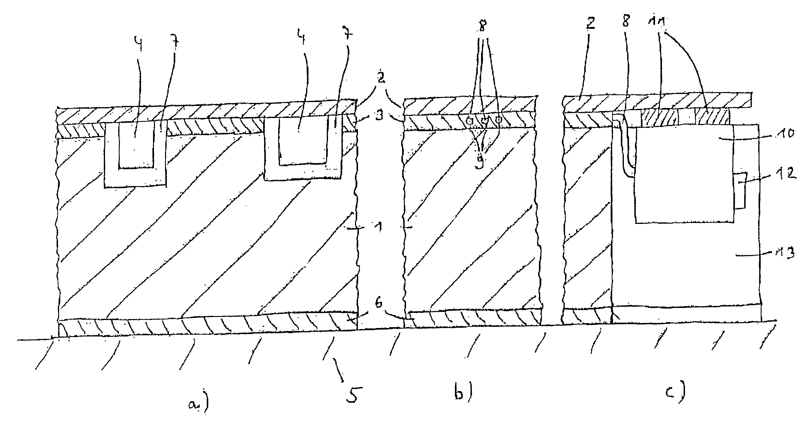
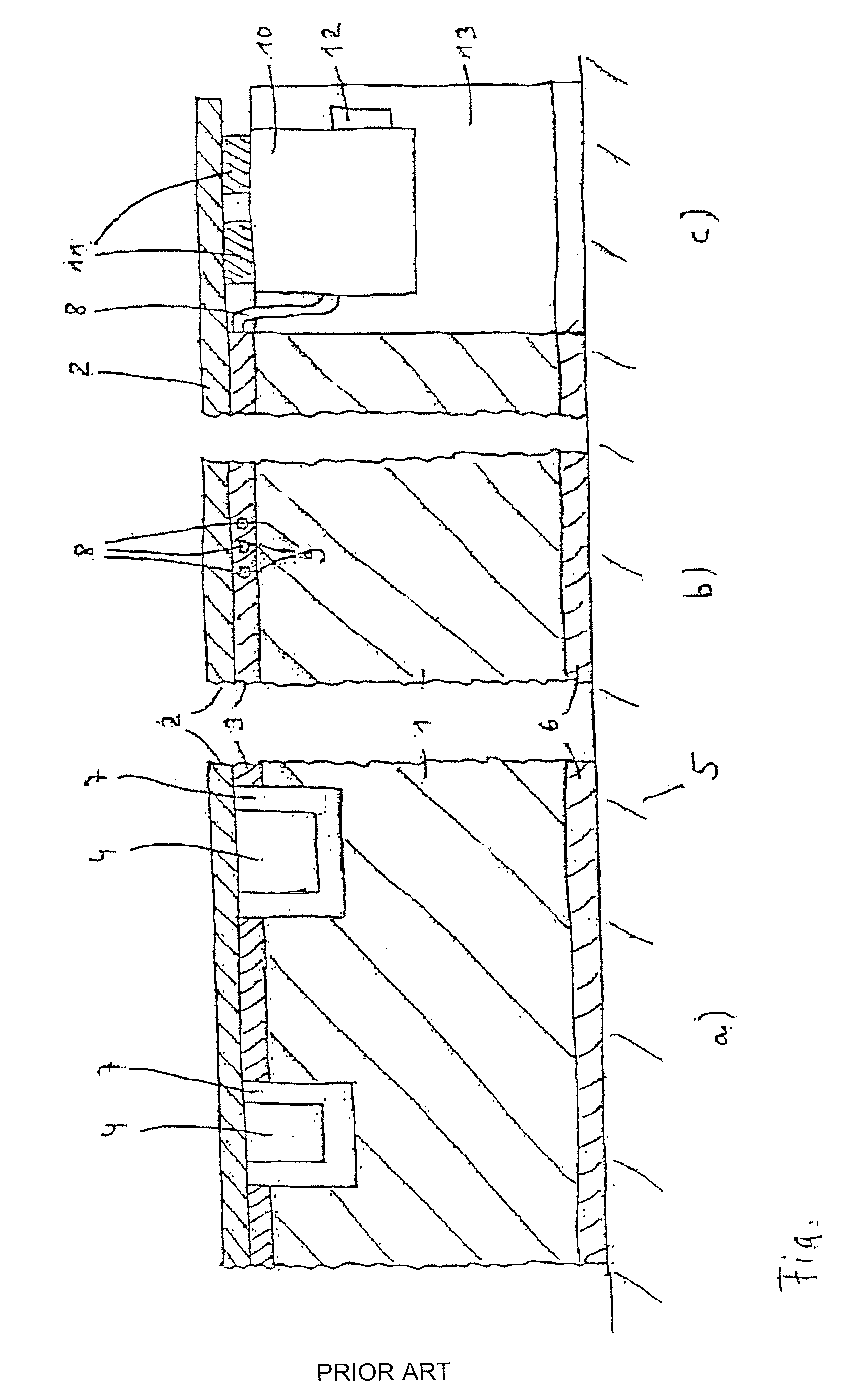
[0031] In practice, the device according to the present invention is also often called a vibrating table. Formwork elements (not shown in the FIGURE) can be built up on the vibrating table that are used to shape the concrete part that is to be manufactured. The formwork elements can be combined arbitrarily in a known manner, so that a more detailed description here is not required.

[0032] A component of the vibrating table is a bearing structure 1 that holds a formwork device 2. Here the table surface or table plate or formwork shell is to be regarded as formwork device 2, which is thus also a component of the overall formwork (made up of table plate / formwork device 2 and the above-described additional formwork elements). The fresh concrete is poured in above formwork device 2.

[0033] Between formwork device 2 and bearing structure 1, a foam layer 3, which acts as a vibration decoupling device, is provided. Foam layer 3 is preferably a viscoelastic layer that can for example also be...


PUM

PropertyMeasurementUnit
Massaaaaaaaaaa
Frequencyaaaaaaaaaa
Compressibilityaaaaaaaaaa

Abstract

The invention relates to a device for compressing concrete during the manufacture of concrete parts. Said device comprises a supporting structure, a formwork device which is maintained by the supporting structure and a vibration decoupling device which is arranged between the supporting structure and formwork device. The vibrations required to compress concrete are produced by a vibration device acting directly upon the formwork device. In order to reduce noise emission, the mass of the supporting structure is selected in such a way that the intrinsic frequency of a system consisting of the supporting structure and vibration decoupling device is lower than the excitation frequency of the vibration device. Preferably, the formwork device, vibration decoupling device, vibrators and all electrical feed lines and connections are premounted, forming a module which can then be mounted on the supporting structure.

Description

BACKGROUND OF THE INVENTION [0001] 1. Field of the Invention [0002] According to the preamble of patent claim 1, the present invention relates to a device for compacting concrete during the manufacture of concrete parts. In addition, according to patent claim 10 the present invention relates to a module intended for installation in such a device. [0003] 2. Description of the Related Art [0004] In the manufacture of concrete parts, the formwork elements in the concrete works are standardly situated on vibrating tables that are used to compress the concrete, which is cast using the formwork elements in order to give it shape. Such a vibrating table is standardly made of a bearing structure made of steel bearers and a steel, wood, or plastic plate (formwork) that acts as a table plate or formwork shell and is held by the bearing structure. The vibrating tables are equipped with an exciter device in the form of several vibration exciters, in particular external vibrators, distributed ov...

Claims


Application Information

Patent Timeline
IPC IPC(8): B28B1/00B28B1/087
CPCB28B1/0873
Inventor SCHULZE, RICHARDMUTH, HOLGER
Owner WACKER NEUSON SE
Why Eureka
Eureka Blog
Learn More