System, method, and kit for positioning a monitor transducer on a patient

a monitor transducer and kit technology, applied in the field of patient monitoring system and method, can solve the problems of loss of one or both signals, inability to use internal monitoring during preterm or early labor, and early sign of possible fetal distress, so as to maximize signal quality and facilitate adjustment. the effect of speed

Inactive Publication Date: 2007-07-19
VAN WYK RACHELLE R +1
View PDF19 Cites 81 Cited by
  • Summary
  • Abstract
  • Description
  • Claims
  • Application Information

AI Technical Summary

Benefits of technology

[0009] It is a further object of the present invention to provide a system, method, and kit wherein the transducer position is maintained during patient movement.
[0010] It is a further object of the present invention to provide a system, method, and kit that allows the position of the transducer to be changed without repositioning the patient.
[0011] It is a further o

Problems solved by technology

Because of this, internal monitoring cannot be used during preterm or early labor and is generally used only after signs of fetal distress are observed through an external monitoring method.
For example, a deceleration or drop in fetal heart rate following a contraction may indicate that the baby is not getting enough oxygen, an early sign of possible fetal distress.
In addition, mothers hospitalized for preterm labor and pregnancy complications often must wear the external fetal monitor continuously for extended periods.
For example, the belts limit the mobility of the mother since movement by the mother frequently causes the positions of the belts and transducers to shift, thereby causing the loss of one or both of the signals.
The loss of the fetal heartbeat signal due

Method used


Image

  • System, method, and kit for positioning a monitor transducer on a patient
  • System, method, and kit for positioning a monitor transducer on a patient
  • System, method, and kit for positioning a monitor transducer on a patient

Examples


Embodiment Construction

[0040] The embodiments described herein are merely intended to illustrate the principles of the invention. Those skilled in the art will recognize that variations and modifications may be made to the embodiments without changing the principles of the invention herein disclosed. Accordingly, the accompanying figures, described in detail below, that depict aspects of the invention are in no way intended to limit the scope of the present invention.

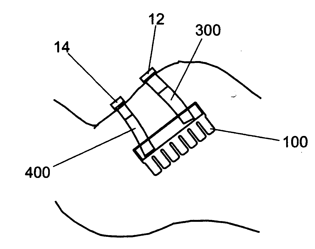
[0041] As used herein, the noted directional terms relate to a human body in a standing position. For instance, “up” refers to in the direction of the head, “down” refers to in the direction of the feet. Herein, the “vertical” direction is parallel to the axis of the body and the “horizontal” direction is parallel to the floor. “Lateral” refers to the direction extending away from the center of the body whereas “medial” refers to a direction extending toward the center of the body.

[0042] The present invention contemplates the use of one or ...


PUM


Abstract

An improved patient monitoring system is described herein. In particular, the present invention provides an improved system, method, and kit for positioning and removably mounting, often repeatedly, a monitor transducer on a patient, for example, an external fetal monitor used during pregnancy and childbirth labor. The improved system of the present invention avoids many of the disadvantages of conventional monitoring systems in that it maintains transducer position during patient movement, allows the position of the transducer to be changed without repositioning the patient, allows for simple and expeditious adjustment so as to maximize signal quality without causing patient discomfort, eliminates the need for a belt circumferentially disposed about the patient's abdomen, and can be applied to a wide array of body types, including patients having round abdomens. The system, method, and kit of the present invention is not only both efficient and effective but also economical.

Description

PRIORITY [0001] This application claims the benefit of provisional application 60 / 682,298 filed May 18, 2005, the contents of which are hereby incorporated by reference in its entirety.TECHNICAL FIELD OF THE INVENTION [0002] The present invention relates to an improved patient monitoring system and method. More particularly, the present invention relates to a system, method and kit for positioning and removably mounting one or more monitor transducers on a patient, for example, an external fetal monitor system used during pregnancy and childbirth labor. BACKGROUND OF THE INVENTION [0003] Fetal monitoring is a valuable tool for monitoring and assessing fetal status and labor progress during pregnancy and childbirth. While there are various types of monitors, all monitor the same signals and assess fetal well-being by measuring parameters such as fetal heart rate and observing the effect of maternal influences, such as labor contractions, on the baby's heart rate. In the modern hospit...

Claims


Application Information

Patent Timeline
IPC IPC(8): A61B8/00
CPCA61B5/02411A61B2562/164A61B5/4356A61B5/4362A61B5/68A61B5/6831A61B7/00A61B8/02A61B8/0866A61B8/4227A61B8/4236A61B8/4281A61B5/6823A61B2503/02A61B5/1107
Inventor VAN WYK, RACHELLE R.VAN WYK, ROBERT A.
Owner VAN WYK RACHELLE R
Why Eureka
Try Eureka