Fiber optic cable with connector

a technology of fiber optic cables and connectors, applied in the field of fiber optic cables, can solve the problems of inability to achieve the effect of maximizing the signal intensity transmitted, and the fiber optic cable typically utilized in the toslink system exhibits a signal loss of 160 decibels per meter,

Inactive Publication Date: 2006-10-17
MEHL RONII C +1
View PDF17 Cites 4 Cited by
  • Summary
  • Abstract
  • Description
  • Claims
  • Application Information

AI Technical Summary

Benefits of technology

[0014]Another object of the present invention is to provide a fiber optic cable which includes ball lenses at each end of the fiber optic cable to maximize signal intensity transmitted through the fiber optic cable.

Problems solved by technology

The fiber optic cable within the TOSLINK system has significant weaknesses.
Specifically, the fiber optic cable typically utilized in TOSLINK systems exhibits a signal loss of 160 decibels per meter.
Any long cable would lose unacceptable amounts of signal intensity.
A second problem with existing TOSLINK fiber optic cable is that it produces “jitter” within the signal.
The plastic fiber within the TOSLINK system is very sensitive and when jitter occurs the sound from the speakers which are driven by the signal passing through the fiber is not pure, but distorted.

Method used


Image

  • Fiber optic cable with connector
  • Fiber optic cable with connector
  • Fiber optic cable with connector

Examples


Embodiment Construction

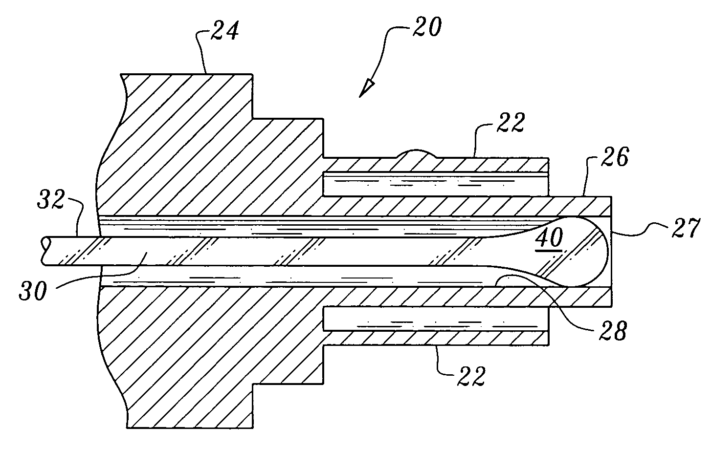
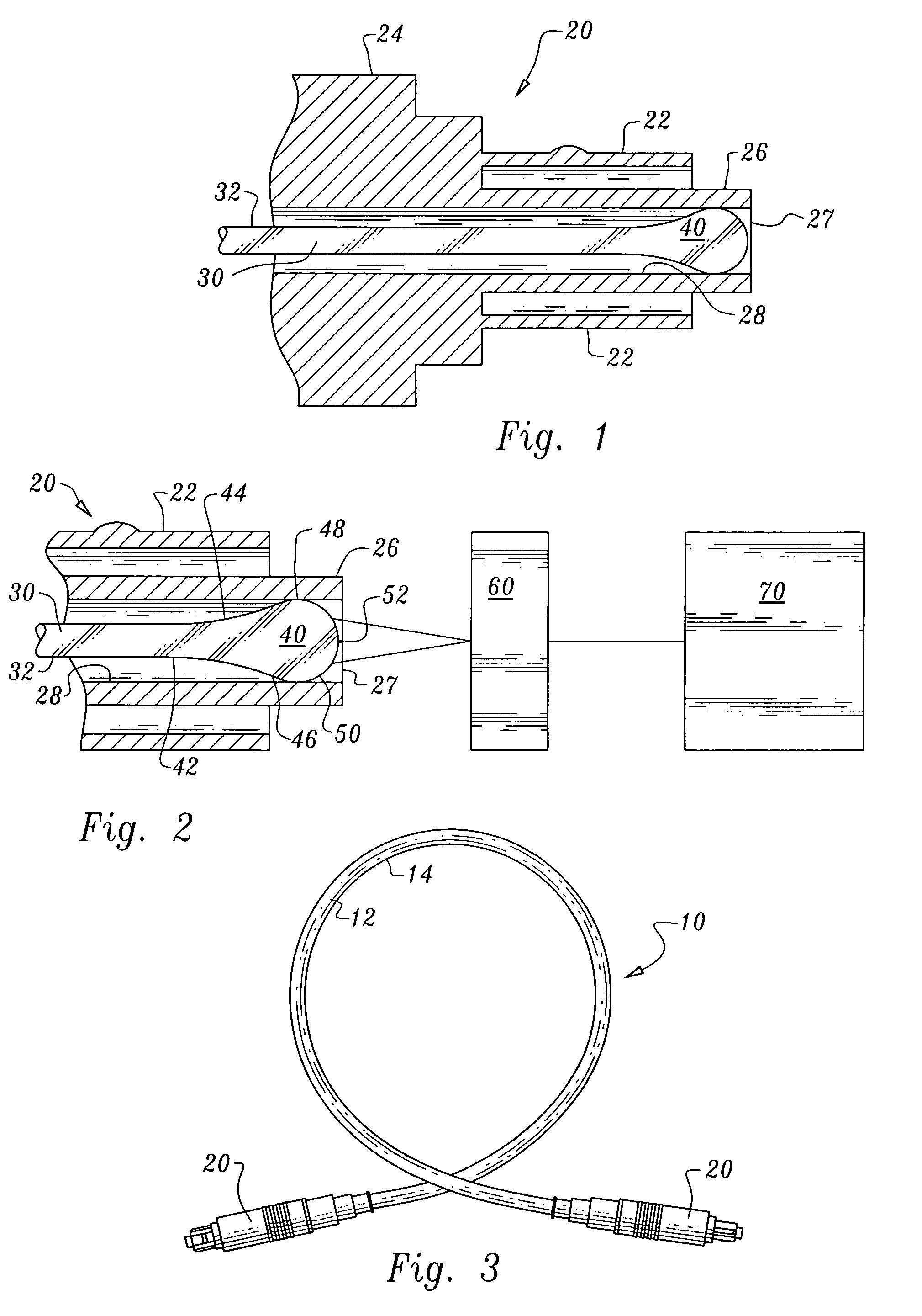
[0026]Referring to the drawings, wherein like reference numerals represent like parts throughout the various drawing figures, reference numeral 10 (FIG. 3) is directed to a cable for transmitting an optical signal between two locations. The cable 10 is particularly configured with suitable fiber connectors 20 to join signal processing components 70 (FIG. 9) together and with an optical signal being transmitted between the separate signal processing components 70. In a preferred embodiment, the cable 10 connects components configured with connectors compatible with a TOSLINK interconnection standard, such as is commonly used to couple audio components together, such as audio receivers and sources of audio sound, such as DVD players.

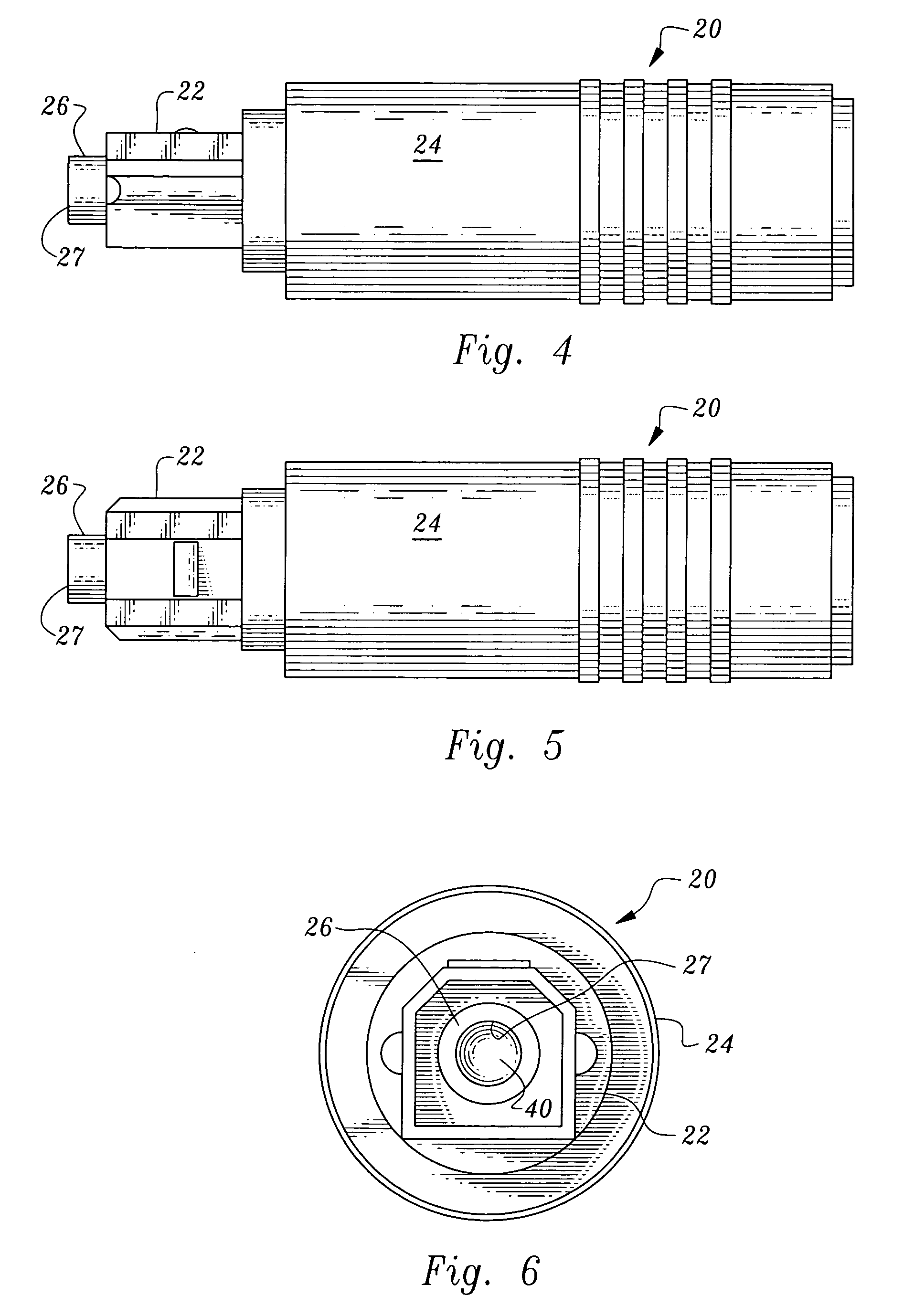
[0027]In essence, and with particular reference to FIGS. 1–3, basic details of the cable 10 are described. The cable 10 provides a run 12 of fiber optic light transmitting fiber 30 extending between a pair of fiber connectors 20 located at terminal ends of...


PUM


Abstract

A fiber optic cable is provided with connectors at terminal ends thereof. The connectors are configured to join TOSLINK compatible components together so that the cable can transmit an optical signal therebetween. A fiber of fused silica glass is provided with a plastic cladding material. Ball lenses are located at each terminal end of the fiber to enhance a signal intensity while maintaining signal quality passing through the cable and between the components joined together by the cable.

Description

FIELD OF THE INVENTION[0001]The following invention relates to fiber optic cable for transmitting a signal between ends of the cable. More particularly, this invention relates to fiber optic cable which includes, in some embodiments, a ball lens or other fiber with enhancement at ends of the cable to enhance signal intensity and overall performance of signals transmission through the cable.BACKGROUND OF THE INVENTION[0002]Fiber optic cable has long been known for transmitting signals between ends of the cable, utilizing a signal encoded with light rather than the signal being encoded with an electric current within an electric conductor. For instance, in telecommunications fiber optic cable is often utilized to transmit large volumes of telecommunications data encoded within light passing through the fiber optic cable.[0003]In one particular application for fiber optic cable, an audio or video signal drives an electrical to optical signal converter which generates light and passes i...

Claims


Application Information

Patent Timeline
Patent Type & Authority Patents(United States)
IPC IPC(8): G02B6/36
CPCG02B6/262G02B6/3869G02B6/4203G02B6/4292G02B6/3887G02B6/38875
Inventor MEHL, RONII C.GEE, JONATHAN R.
Owner MEHL RONII C
Why Eureka
Try Eureka