Radio communication system

a communication system and radio technology, applied in the field of radio communication systems, can solve the problems of disadvantageous time-consuming and laborious to achieve synchronization for communication, and degrade communication performance, so as to improve communication performance, prevent the degraded communication performance, and shorten the time

Inactive Publication Date: 2007-09-06
PANASONIC CORP
View PDF2 Cites 2 Cited by
  • Summary
  • Abstract
  • Description
  • Claims
  • Application Information

AI Technical Summary

Benefits of technology

[0018]In the fourth aspect of the invention, in the first state, the band pass filter receives the oscillation output signal of the local oscillator, and at this point, a frequency band for maximizing the signal intensity is learned on the basis of the discrimination result of the discriminating unit for receiving the output of the band pass filter. In the second state, the frequency band learned in the first state is set in the band pass filter, and the filtering operation is performed on the input signal. Thus, a shift of the frequency band of the band pass filter can be corrected. In addition, there is no need to send a pilot signal from a transmitting side for this shift correction.
[0019]As described above, according to the present invention, the shift of the frequency band of the low noise amplifier or the band pass filter can be corrected. In addition, there is no need to send a pilot signal from a transmitting side for this shift correction. Accordingly, degradation of the communication performance can be prevented in a short period of time, resulting in improving the communication performance.

Problems solved by technology

In the conventional method, however, there is a problem that the communication performance is degraded when the frequency band of a signal amplified by the low noise amplifier and the hopping frequency of the local oscillator are shifted from each other.
Furthermore, it is necessary to transmit a pilot signal from a transmitter for correcting the shift, and hence, it disadvantageously takes time to attain synchronization for starting communication.

Method used


Image

  • Radio communication system
  • Radio communication system
  • Radio communication system

Examples


embodiment 1

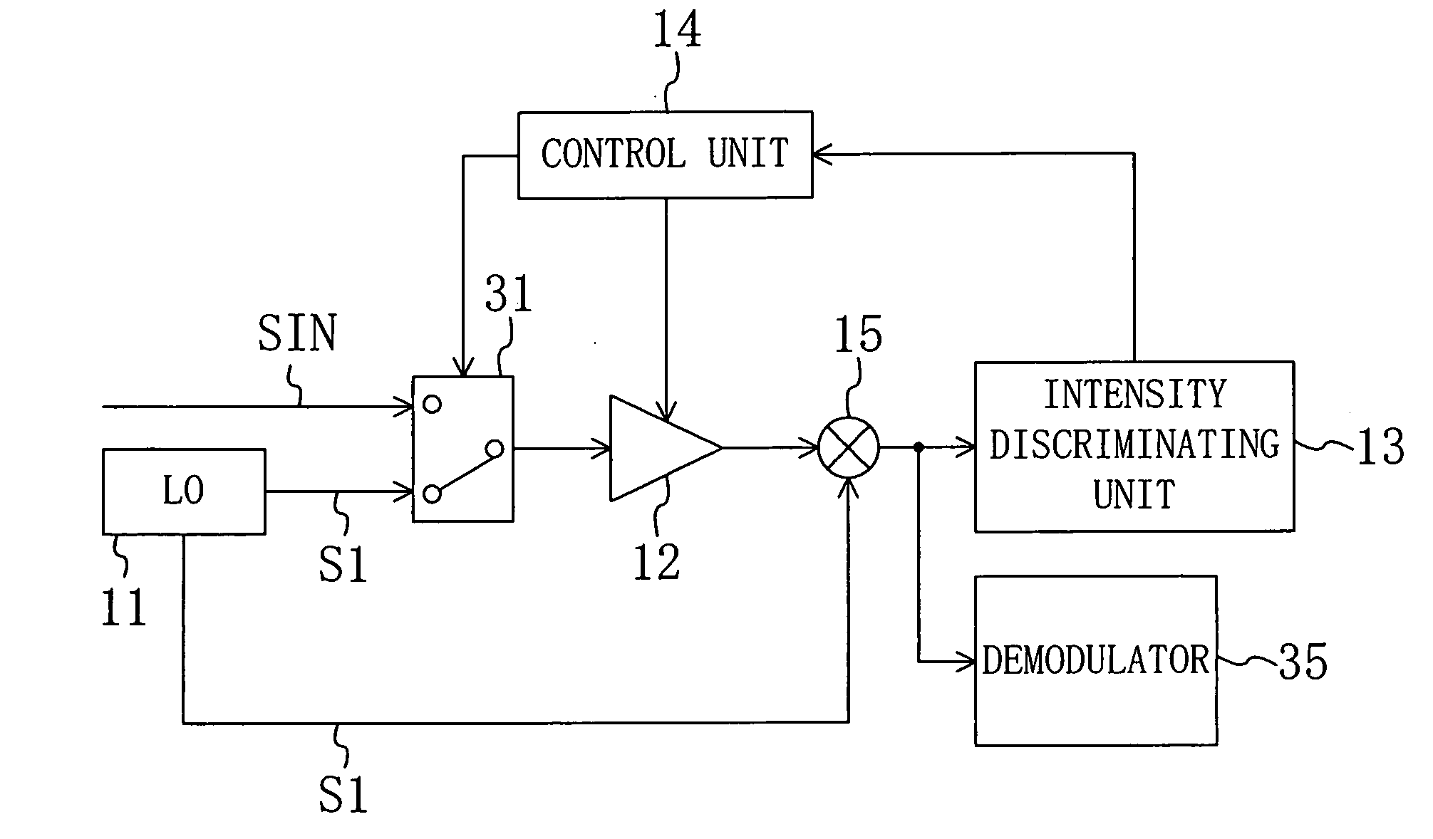
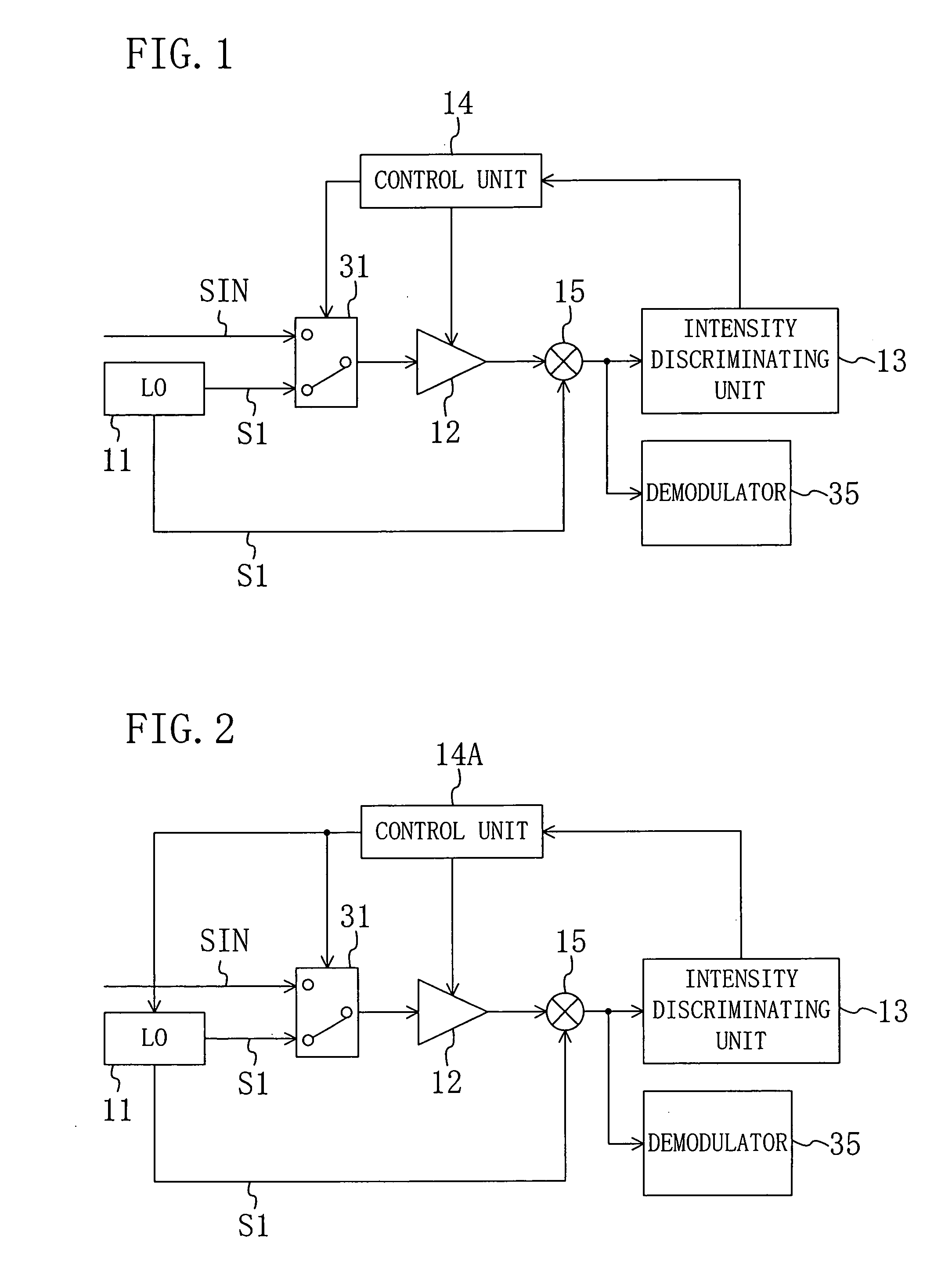
[0027]FIG. 1 is a diagram for showing the architecture of a radio communication system according to Embodiment 1 of the invention. In FIG. 1, a reference numeral 11 denotes a local oscillator (LO), a reference numeral 12 denotes a low noise amplifier (LNA) capable of hopping a frequency band to be amplified, a reference numeral 13 denotes an intensity discriminating unit for discriminating signal intensity, a reference numeral 14 denotes a control unit for controlling a frequency band of the low noise amplifier 12, a reference numeral 15 denotes a mixer for integrating an oscillation output signal S1 of the local oscillator 11 and an output signal of the low noise amplifier 12, a reference numeral 31 denotes a selection unit receiving an input signal SIN and the oscillation output signal S1 of the local oscillator 11 as inputs for selectively outputting one of them, and a reference numeral 35 denotes a demodulator for demodulating an output signal of the mixer 15.

[0028]The control u...

embodiment 2

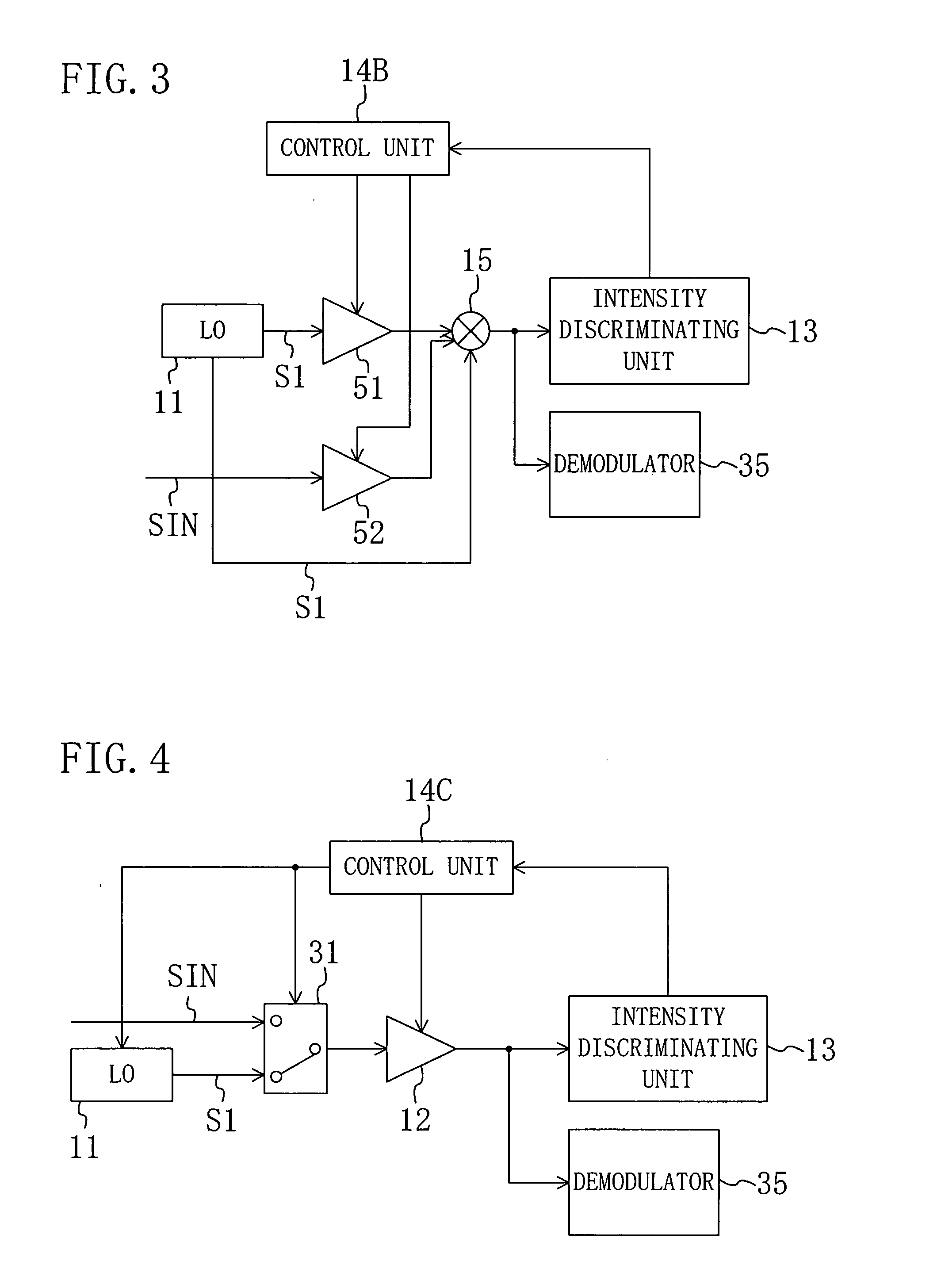
[0034]FIG. 3 is a diagram for showing the architecture of a radio communication system according to Embodiment 2 of the invention. In FIG. 3, like reference numerals are used to refer to like elements shown in FIG. 1. As compared with the architecture of FIG. 1, first and second low noise amplifiers 51 and 52 each capable of hopping the frequency band to be amplified are provided in FIG. 3 instead of the low noise amplifier 12 and the selection unit 31. The first low noise amplifier 51 receives and amplifies an output signal S1 of a local oscillator 11. On the other hand, the second low noise amplifier 52 receives and amplifies an input signal SIN. A control unit 14B controls the amplification operations and the frequency bands of the first and second low noise amplifiers 51 and 52, and a mixer 15 integrates the output signal S1 of the local oscillator 11 and an output signal of the first or second low noise amplifier 51 or 52.

[0035]The operation of the radio communication system ha...

embodiment 3

[0041]In Embodiment 3 of the invention, the present invention is applied to a communication system in which frequency shift by using a mixer is not performed.

[0042]FIG. 4 is a diagram for showing the architecture of a radio communication system according to Embodiment 3 of the invention. In FIG. 4, like reference numerals are used to refer to like elements shown in FIG. 1. As compared with the architecture of FIG. 1, a mixer 15 is omitted, an intensity discriminating unit 13 discriminates the signal intensity of an output of a low noise amplifier 12, and a demodulator 35 receives and demodulates the output of the low noise amplifier 12 in the architecture of FIG. 4.

[0043]In employing the architecture of FIG. 4, in the communication system where no mixer is used, a pulse signal is once input to a band pass filter to select a frequency component and then output from an antenna on a transmitting side. On the other hand, for amplifying a signal received at an antenna on a receiving side...


PUM


Abstract

The communication performance of a radio communication system is improved while keeping short time necessary for attaining synchronization. A low noise amplifier is selectively provided with one of an input signal supplied from the outside of the system and an oscillation output signal of a local oscillator. A mixer integrates the oscillation output signal of the local oscillator and an output signal of the low noise amplifier. An intensity discriminating unit discriminates the signal intensity of an output of the mixer. In a first state, the low noise amplifier amplifies the oscillation output signal of the local oscillator, and a control unit learns a frequency band of the low noise amplifier for maximizing the signal intensity on the basis of the discrimination result of the intensity discriminating unit. In a second state, the low noise amplifier is set to the frequency band learned in the first state and amplifies the input signal.

Description

CROSS-REFERENCE TO RELATED APPLICATIONS[0001]This application claims priority under 35 U.S.C. § 119 on Patent Application No. 2006-54452 filed in Japan on Mar. 1, 2006, the entire contents of which are hereby incorporated by reference.BACKGROUND OF THE INVENTION[0002]The present invention relates to a radio communication system correlated with, for example, UWB (Ultra Wide Band) communication or the like using signals of a ultra wide frequency band.[0003]Recently, in accordance with rapid increase of information content, there are increasing demands for a large capacity and a high speed for interchange and transmission of information data. In order to meet such demands, techniques relating to radio communication are being rapidly developed.[0004]The radio communication is now spreading in offices and homes because there is no need to provide cables and the like. In particular, UWB communication expected for communication with small power consumption is regarded as a promising commun...

Claims


Application Information

Patent Timeline
Patent Type & Authority Applications(United States)
IPC IPC(8): H04B1/16H04B1/18H04J11/00
CPCH04L27/2647H04B1/713
Inventor WATANABE, MANABUYAMAOKA, YUUSUKE
Owner PANASONIC CORP
Why Eureka
Try Eureka