
Debugging device using an lpc interface capable of recovering functions of bios, and debugging method therefor

a technology of bios and debugging device, which is applied in the field of debugging device and debugging method thereof, can solve the problems of saving cost and time spent on debugging device in recovering bios, and achieve the effects of reducing cost, reducing space occupation, and high compatibility

Inactive Publication Date: 2007-07-19
INVENTEC CORP
View PDF3 Cites 22 Cited by
  • Summary
  • Abstract
  • Description
  • Claims
  • Application Information

AI Technical Summary

Benefits of technology

[0008] Therefore, it is an object of the present invention to provide a debugging device using an LPC interface and capable of recovering the BIOS functions. The debugging device saves cost and time spent in recovering the BIOS and replacing the BIOS component through the equipment. In addition, the debugging device extracts the POST code to monitor the startup state of the computer system through the LPC interface. Accordingly, the compatibility of the debugging device is improved and the component space is decreased.
[0009] It is another object of the present invention to provide a debugging device using an LPC interface and capable of recovering the BIOS functions. The debugging device can monitor the startup state of the computer system in real time, and save the cost spent in reprogramming the BIOS and replacing the BIOS component through the special equipment.
[0010] It is yet another object of the present invention to provide a debugging method for recovering the BIOS functions by using an LPC interface. The debugging method can recover the BIOS with a minimum cost and time, and also monitor the startup state of the computer system in real time through the LPC interface with high compatibility.
[0017] In the present invention, a structure of using the LPC interface and the firmware hub to recover the BIOS and obtaining the POST code is applied. Accordingly, the firmware hub can recover the damaged BIOS with a minimum cost and time in real time, and the POST code is obtained through the LPC interface that has a high compatibility and smaller space to recognize the startup state of the computer system.

Problems solved by technology

The debugging device saves cost and time spent in recovering the BIOS and replacing the BIOS component through the equipment.

Method used


Image

  • Debugging device using an lpc interface capable of recovering functions of bios, and debugging method therefor
  • Debugging device using an lpc interface capable of recovering functions of bios, and debugging method therefor
  • Debugging device using an lpc interface capable of recovering functions of bios, and debugging method therefor

Examples


Embodiment Construction

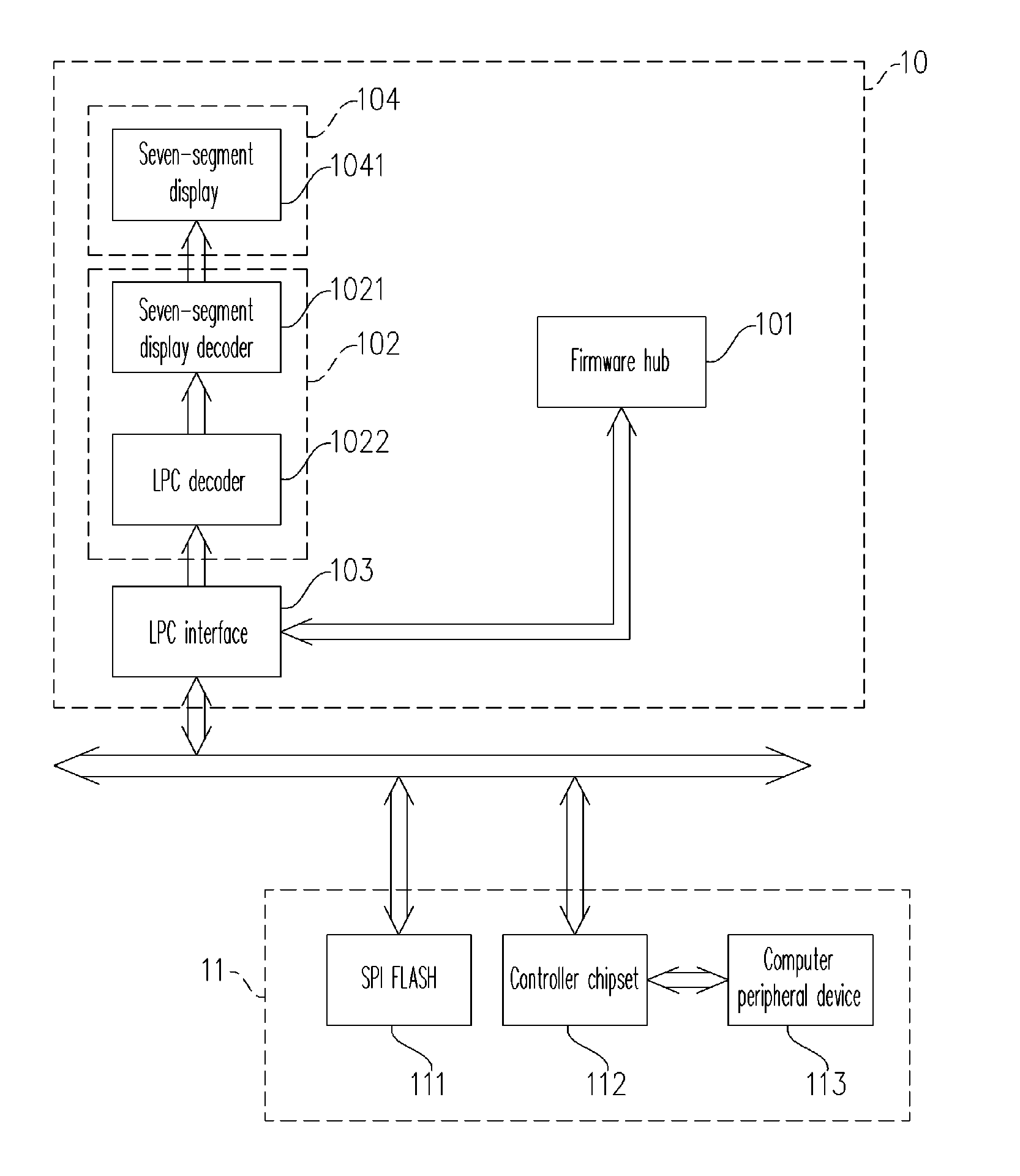
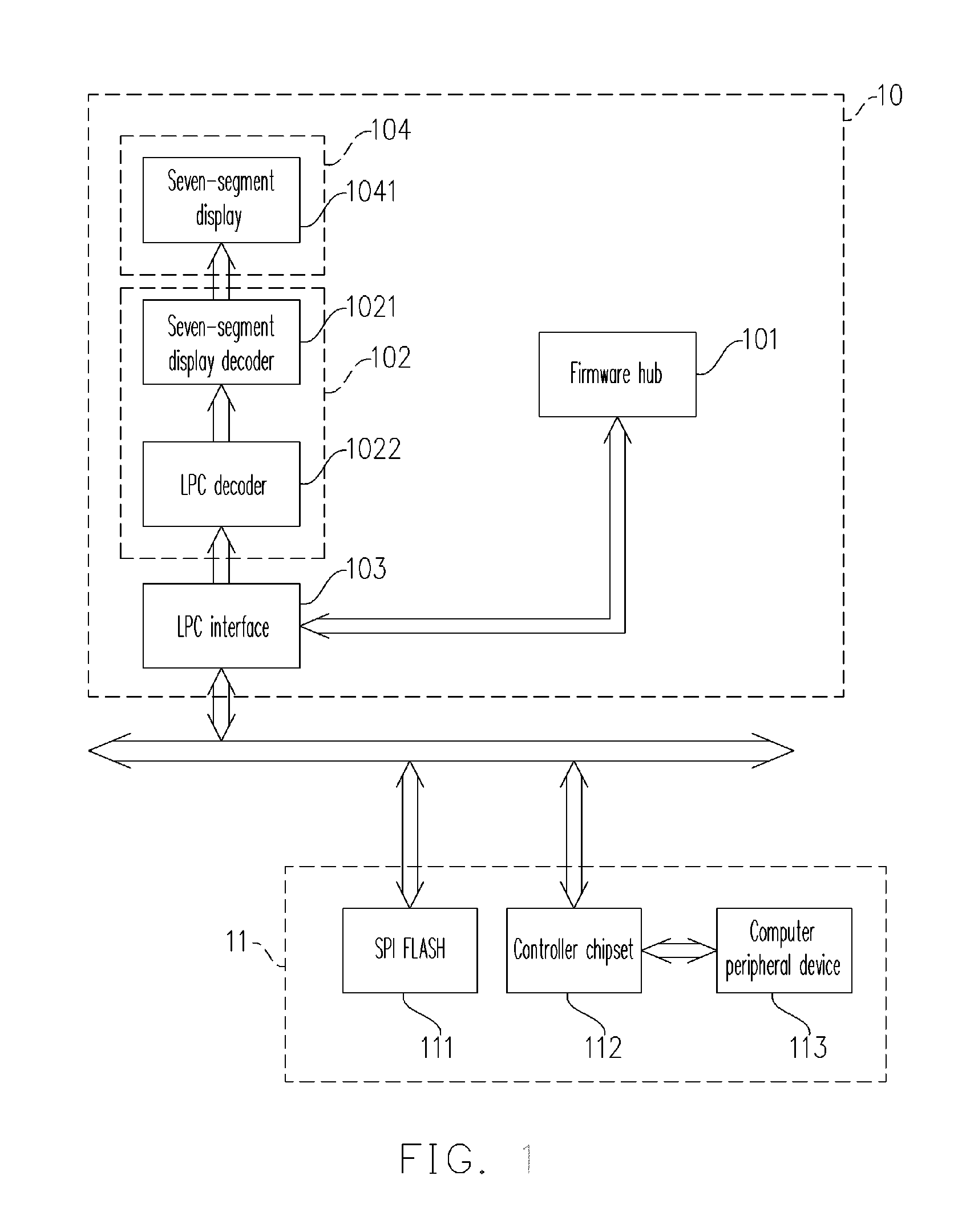
[0022]FIG. 1 is a circuit diagram of a debugging device using an LPC (low pin count) interface and capable of recovering the BIOS (basic input / output system) functions according to an embodiment of the present invention. The debugging device 10 comprises a firmware hub 101, a decoder 102, an LPC (low pin count) interface 103, and a display unit 104. The debugging device 10 uses the display unit 104 to display the startup error state of a computer system 11 and recovers the error BIOS code in the SPI (serial peripheral interface) FLASH that fails to startup.

[0023] The computer system 11 comprises the SPI FLASH 111, a controller chipset 112, and a computer peripheral device 113. The original BIOS stored in the SPI FLASH 111 is transmitted to the controller chipset 112 through the LPC bus, such that the computer system can successfully power up. When the computer system is starting up, the controller chipset 112 performs a power test on the computer peripheral device 113 and sends out...


PUM


Abstract

The present invention discloses a debugging device using an LPC interface and capable of recovering the BIOS functions and a debugging method therefor. The debugging device comprises a firmware hub, an LPC interface, a decoder, and a display unit. The LPC interface electrically connects to the decoder, the firmware hub, and a computer system. The decoder receives a POST code of the computer system to monitor a startup state of the computer system through the LPC interface, and then decodes and provides the decoded POST code to the display unit for showing every startup step of the computer system. When the original BIOS of the computer system is damaged, the firmware hub provides a backup BIOS for the computer system to start up, and recovers the original damaged BIOS. The present invention improves the stability of the computer system, and saves the cost and time of recovering the BIOS.

Description

CROSS-REFERENCE TO RELATED APPLICATION [0001] This application claims the priority benefit of Taiwan application serial no. 94143541, filed on Dec. 9, 2005. All disclosure of the Taiwan application is incorporated herein by reference. BACKGROUND OF THE INVENTION [0002] 1. Field of the Invention [0003] The present invention relates to a debugging device and a debugging method thereof, and more particularly, to a debugging device using an LPC interface capable of recovering functions of BIOS and a debugging method therefor. [0004] 2. Description of the Related Art [0005] The conventional debugging card receives a POST (power on self test) code to display the debugging message through the PCI (peripheral component interconnection) bus interface or the MINI PCI (mini peripheral component interconnection) interface. Wherein, the POST code is the result of the power test on every component of the computer system when the computer system is booted up. For example, the POST code represents ...

Claims


Application Information

Patent Timeline
IPC IPC(8): G06F11/00
CPCG06F11/2284
Inventor LEE, WEI-MINGLIU, DICK
Owner INVENTEC CORP
Learn More