Oil pan for an internal combustion engine

a technology for internal combustion engines and oil pans, applied in the field of oil pans, can solve the problems of insufficient fluid tightness, inability to achieve reliable fluid tightness, and high cost of measures, and achieve the effect of improving the self-locking

Inactive Publication Date: 2007-07-26
MANN HUMMEL GMBH
View PDF8 Cites 21 Cited by
  • Summary
  • Abstract
  • Description
  • Claims
  • Application Information

AI Technical Summary

Benefits of technology

[0007] This embodiment has the advantage that a thread is not required in the wall of the oil pan bordering the drain openings, so it is possible to use oil pans made of metal having very thin walls as well as oil pans made of synthetic resin material. The absence of a thread in the drain opening represents a considerable simplification from a design standpoint.
[0008] In accordance with one advantageous embodiment, the valve body executes an axial lifting movement during the transfer movement between its closed position and its open position, this axial movement being combined with a rotational movement, whereby the transfer between the closed position and the open position of the valve body is advantageously implementable with the help of simple control elements and can be performed from outside of the oil pan in particular. The valve body may be moved manually—optionally with the help of a control element—into the open position by an external component, e.g., a tool, thereby opening the drain opening and allowing the oil to escape from the pan. For a tight fit in the drain opening, it may be advantageous here for the sealing member to be arranged in the area of the end face o

Problems solved by technology

In the case of oil pans made of synthetic resin material, the required imperviousness can hardly be established merely by a screw connection of the oil drain plug to the wall of the oil pan because only a limited introduction of force is possible for strength reason

Method used


Image

  • Oil pan for an internal combustion engine
  • Oil pan for an internal combustion engine
  • Oil pan for an internal combustion engine

Examples


Embodiment Construction

[0018] In the figures, corresponding components are identified by the same reference numerals.

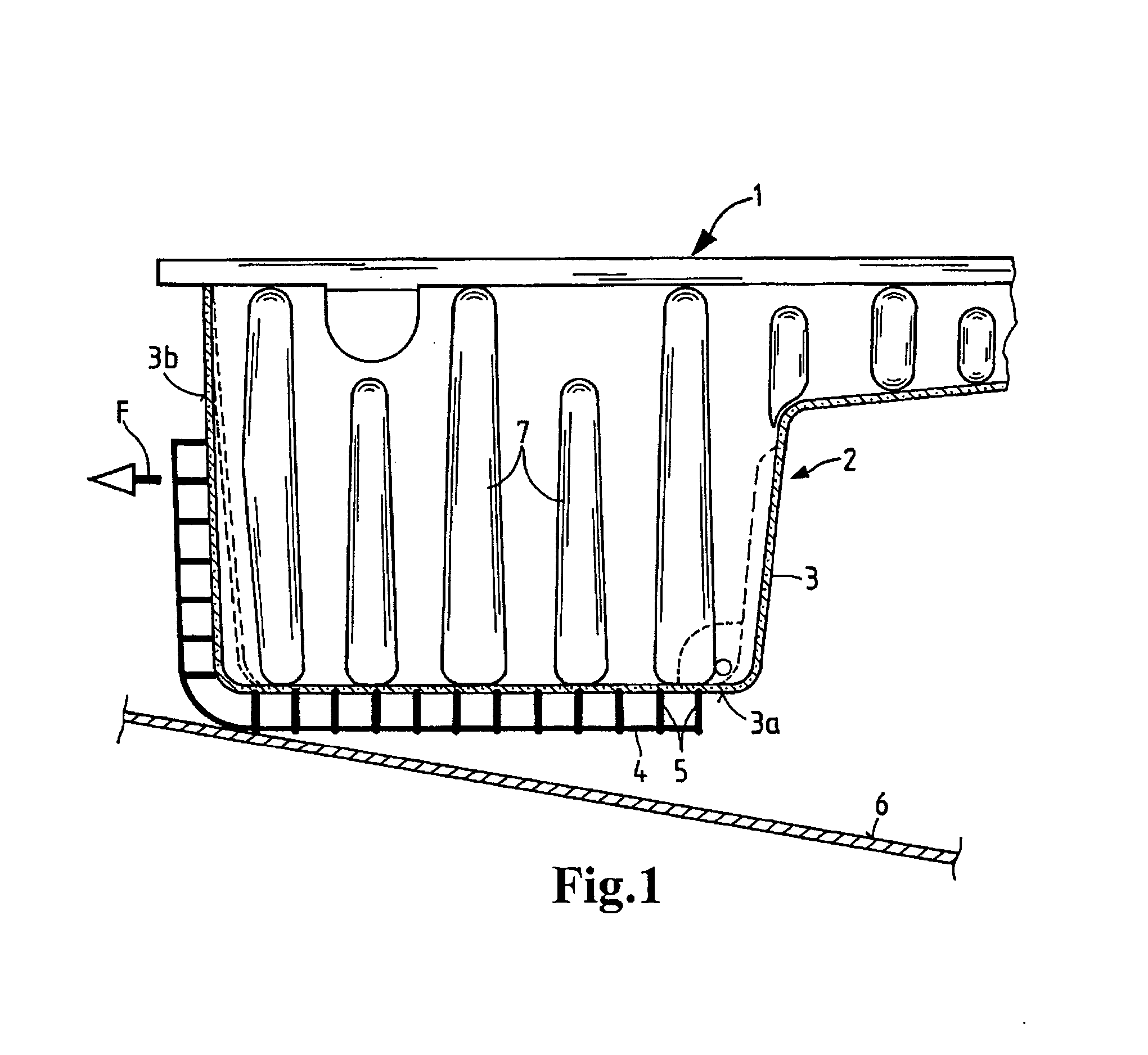
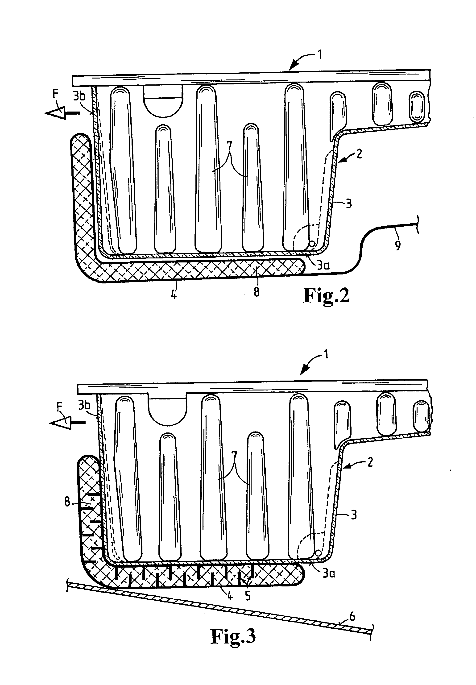
[0019] The oil pan 1 for an internal combustion engine of a motor vehicle as illustrated in FIG. 1 has an oil pan housing 2 made of synthetic resin material manufactured, in particular, by an injection molding process. The outside wall 3 of the oil pan housing 2 comprises a pan bottom 3a at the bottom and peripheral side walls 3b. The pan bottom 3a and the side walls 3b, which are at the front in the forward direction F of the vehicle, are surrounded by a protective wall and / or shell 4 which is constructed as a separate component and is connected to the pan bottom 3a and / or the front side wall 3b by spacer elements 5. The spacer elements 5 ensure that the protective shell 4 is spaced a distance from the outside wall 3 of the oil pan housing 2, so that an intermediate space is formed between the outside wall 3 and the protective shell 4. The protective shell 4 and the spacer elements 5 adva...


PUM


Abstract

An oil pan having a drain mechanism (10) that comprises an adjustable valve body (11) which is introduced into a drain opening (13) in an oil pan wall and which is adjustable between a closed position and an open position. A sealing member (12) made of a flexible material is arranged on the valve body (11) of the drain mechanism (10) for closing the drain opening (13) in the wall of the oil pan (1) when the valve body is in the closed position, and the valve body (11) when in the closed position is secured against the wall of the oil pan (1) by a closing element, and the sealing member (12) is held in the closed position by the closing element.

Description

BACKGROUND OF THE INVENTION [0001] The present invention relates to an oil pan, in particular for an internal combustion engine, having a drain mechanism comprising a valve body which is inserted into a drain opening in an oil pan wall and which is adjustable between closed and open positions. [0002] Oil pans of this type, which are arranged on the underside of an internal combustion engine, must be designed to be stable to withstand high forces, and also to withstand high mechanical forces to which they may be subjected, for example, from a stone strike or from the vehicle scraping the ground. There are also known embodiments of oil pans made of metal or even a one-piece injection-molded part made of polyamide or polypropylene, as described in published European patent application no. EP 1,041,253. To be able to drain the oil out of the oil pan, a drain opening is provided in the bottom of the pan which can be closed by an adjustable closing element. In the case of oil pans made of...

Claims


Application Information

Patent Timeline
IPC IPC(8): F16K31/44
CPCF01M11/0004F01M2011/0416F01M2011/0091F01M11/0408
Inventor JESSBERGER, THOMAS
Owner MANN HUMMEL GMBH
Why Eureka
Try Eureka