
Piston for capsule, method of forming such piston, and capsule therewith

a technology of plunger and plunger, which is applied in the direction of teeth capping, amalgam press/mixer, dental prosthetics, etc., can solve the problems of material being pulled away from the tooth surface, voids in fillings, and considerable difficulties for dental professionals in accurate placement of such materials into or onto patients' teeth, so as to minimize the formation of voids in patient's tooth restorations, avoid relatively large dead spaces, and minimize material waste

Inactive Publication Date: 2007-07-26
3M ESPE
View PDF43 Cites 81 Cited by
  • Summary
  • Abstract
  • Description
  • Claims
  • Application Information

AI Technical Summary

Benefits of technology

[0061] It is an advantage of the present invention to be able to provide a piston which avoids relatively large dead spaces particularly in front portions of capsules where material remains after use. The present invention thus minimizes waste of material for conventional capsules used for dental materials, such as dental filling materials.
[0062] The present invention has the further preferred advantages of providing a capsule construction particularly suitable for effecting the placement of ultra-dense or highly-filled composite resin dental materials by the syringing technique. Moreover, the formation of voids in a patient's tooth restoration are minimized because the material can be directed to the bottom of a cavity and filled from that point outward.

Problems solved by technology

As a result, dental professionals encountered considerable difficulties in the accurate placement of such a material into or onto a patient's tooth.
The dental professional applied the material to the tooth with a spatula or similar tool, but this technique sometimes resulted in the filling having voids within the final restoration, which is undesirable because voids affect the strength of the filling.
Voids could be caused either by the inability of the user to pack such a material into small areas of a tooth that are difficult to reach, or by the entrainment of air and thus the formation of air bubbles in the composite material as it was being placed.
A further difficulty that was encountered by the dentist was that such composite material had a tendency to stick to the palate or spatula, causing the material to be pulled away from the tooth surface when the dentist removed the palate or spatula.
Also, if a dentist used a metal instrument to place the composite material, there was a tendency of the instrument to react with and discolour the composite.
With conventional capsule constructions, it is typically not possible to dispense substantially all of the dental material from the capsule.
Because tooth filling materials are relatively expensive, this waste is costly.
However, high forces would be required to dispense these materials through a capsule having a discharge nozzle with a small passageway.
Therefore those highly viscous materials are typically used with capsules having a rather large passageway, in which on the other hand a higher amount of wasted paste remains after the capsule has been used.

Method used


Image

  • Piston for capsule, method of forming such piston, and capsule therewith
  • Piston for capsule, method of forming such piston, and capsule therewith
  • Piston for capsule, method of forming such piston, and capsule therewith

Examples


Embodiment Construction

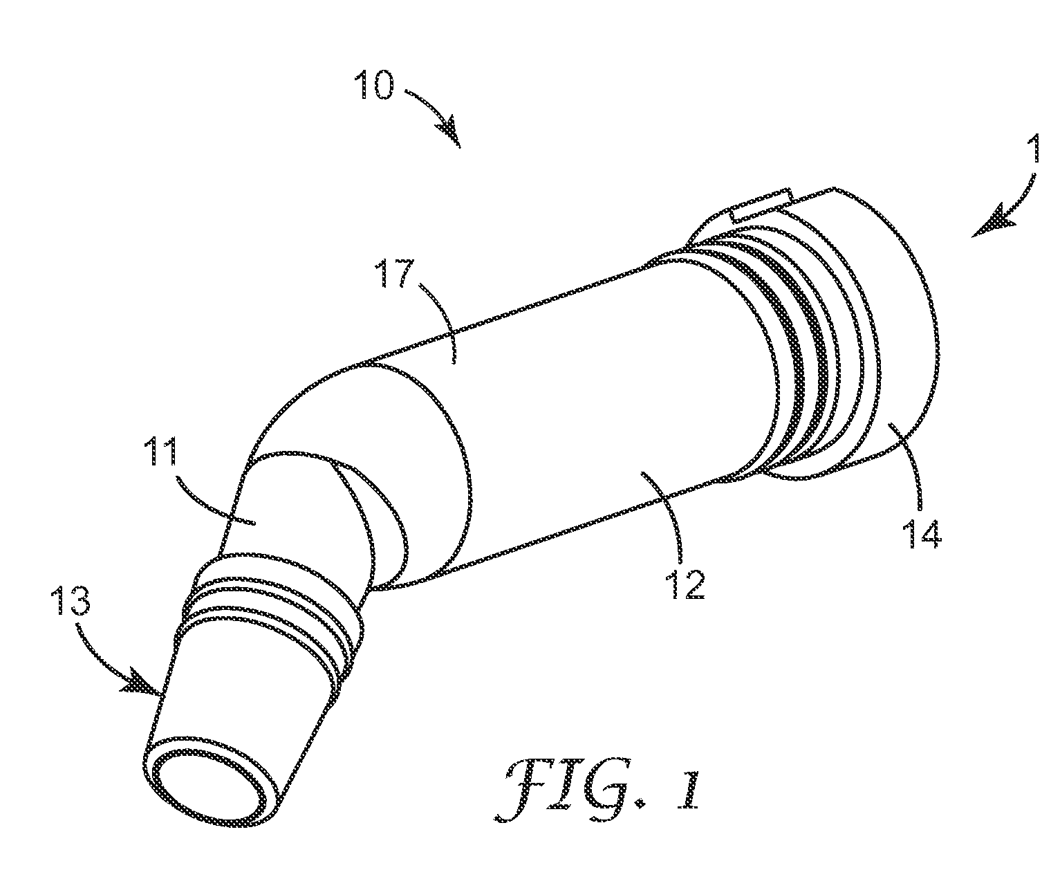
[0075]FIG. 1 shows capsule 10 with a barrel 17 having a front portion 11 and a rear portion 12.

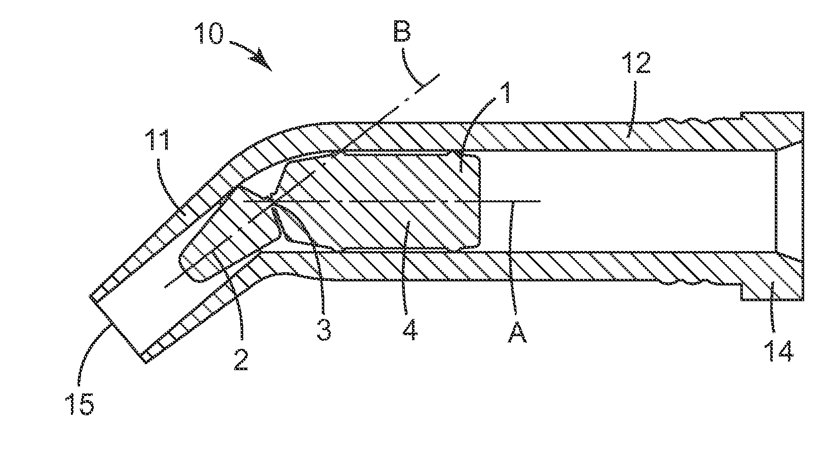
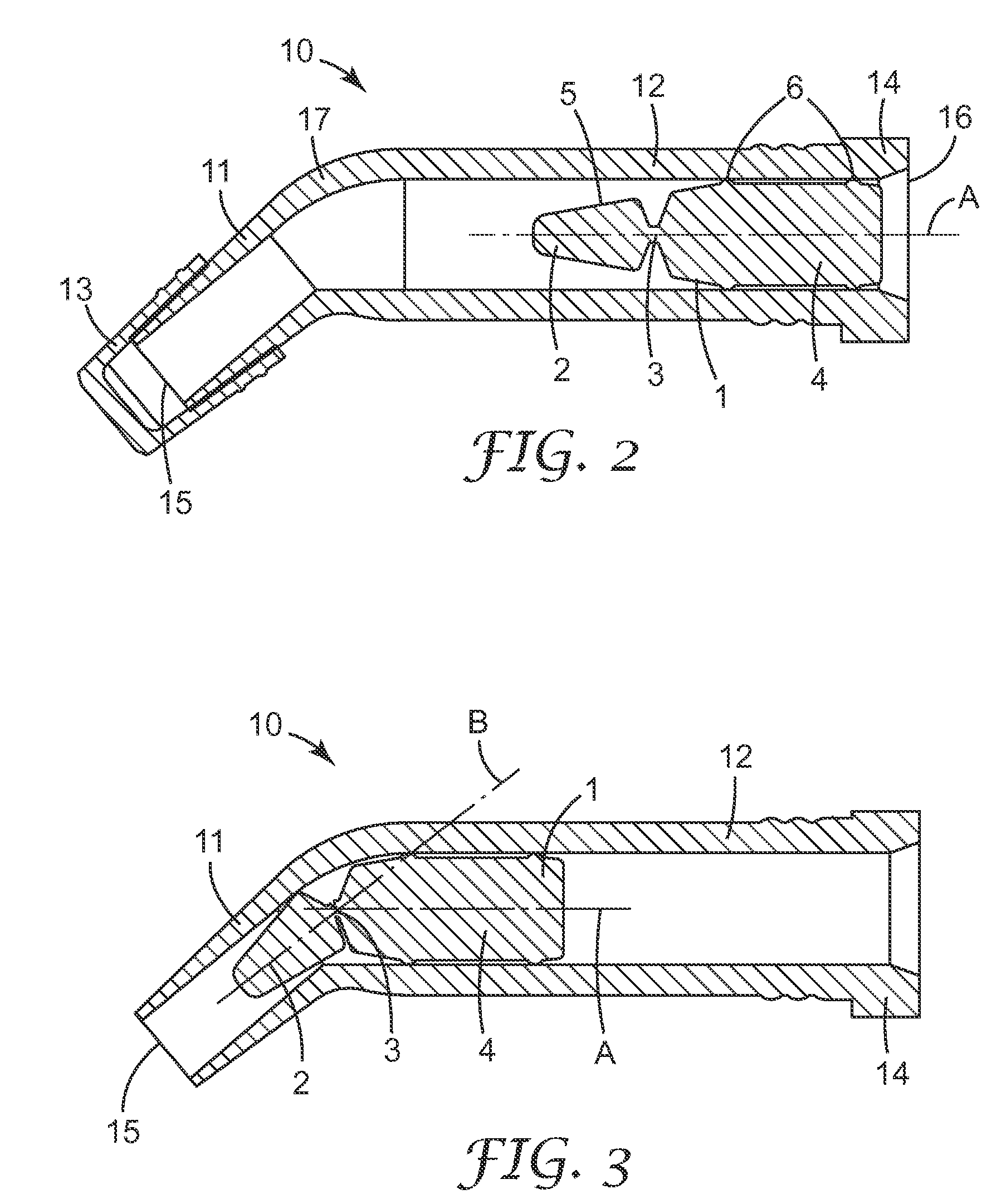
[0076] FIGS. 2 to 9 show a cross-section through the capsule 10 with a piston 1 of different embodiments and at different positions.

[0077] As shown in FIGS. 2 and 3, the piston 1 has at least a front section 2 with a longitudinal axis B (FIG. 3) and a rear section 4 with a longitudinal axis A. The piston 1 further has one or more surface(s) 5 which is or are the surface(s) facing the material stored in the barrel 17. In embodiments in which the piston 1 has one or more slots, grooves, or other structures provided (as described above), the available volume and extent of the surfaces may be larger due to those structures. The piston 1 shown has a circular cross-section, but can also have a non-circular cross-section. The barrel 17 normally has a cross-sectional shape corresponding to the cross-sectional shape of the piston 1. It may also be possible that the piston itself is for example cy...


PUM


Abstract

The invention is directed to a piston or plunger (1) for a material delivery system (10) and a delivery system (10), such as a cartridge delivery system or syringe for storage and dispensing of a viscous or pasty material, in which the system includes a piston or plunger (1). The piston or plunger (1) is preferably provided for a unit dose dental capsule for the direct placement of a dental material, such as a light-curable tooth filling material, into a desired location.

Description

CROSS-REFERENCE TO RELATED APPLICATIONS [0001] This application claims priority from European Patent Application No. 06001465.1, filed Jan. 24, 2006. FIELD OF THE INVENTION [0002] The invention is directed to a piston or plunger for a material delivery system and a delivery system, such as a cartridge delivery system or syringe for storage and dispensing of a viscous or pasty material, in which the system includes a piston or plunger. The piston or plunger is preferably provided for a unit dose dental capsule for the direct placement of a dental material, such as a light-curable tooth filling material, into a desired location. BACKGROUND OF THE INVENTION [0003] Dental materials for restoring teeth often have a pasty consistency. As a result, dental professionals encountered considerable difficulties in the accurate placement of such a material into or onto a patient's tooth. The dental professional applied the material to the tooth with a spatula or similar tool, but this technique ...

Claims


Application Information

Patent Timeline
Patent Type & Authority Applications(United States)
IPC IPC(8): A61C5/04A61C5/66
CPCA61C5/062A61C5/066B05C17/00576B05C17/00516B05C17/0052A61C9/0026A61C5/62A61C5/66
Inventor MULLER, THOMAS K.HAUTMANN, MARIKAWAGNER, INGO W.
Owner 3M ESPE
Learn More