Hospital bed

a technology for supporting equipment and beds, which is applied in the direction of beds, tables, transportation and packaging, etc., can solve the problems of inability to move the bed, the weight of present day beds and patients is relatively large, and the manual or motor-driven mechanism used to raise and lower the fowler section moves too slowly to be acceptable in an emergency situation, etc., to achieve the effect of raising the upper arm portion and the lower arm portion

Inactive Publication Date: 2007-08-02
STRYKER CORP
View PDF75 Cites 226 Cited by
  • Summary
  • Abstract
  • Description
  • Claims
  • Application Information

AI Technical Summary

Benefits of technology

[0024] According to another aspect, the force transfer devices each have upper and lower lift arms, each lift arm having upper and lower portions, each portion having upper and lower pivots, each transfer device having a lower rotatable gear, a lower stationary gear, an upper rotatable gear, a first connecting member engaging the lower rotatable gear and the upper rotatable gear, and a second connecting member adapted to engage the lower stationary gear and the upper rotatable gear. An actuator causes the lower rotatable gear to move the first connecting member, the first connecting member causes the upper rotatable gear to rotate, the upper rotatable gear, simultaneously causing the upper arm to pivot upwardly about the lower pivot of the upper arm portion and causing the second connecting member to transmit a pivoting force to the lower arm portion, thus pivotably raising the lower arm portion. According to another aspect, the upper rotatable gear comprises a first gear and a second gear, the first gear concentric with the second gear, and the first gear fixed to the second gear. The first gear engages the first connecting member and the second gear engages the second connecting member. To effect a gear reduction system, the lower rotatable gear may be smaller than the first gear of the upper rotatable gear, and the second gear of the upper rotatable gear may be smaller than the lower stationary gear.
[0025] According to another aspect, the force transfer devices each have upper and lower lift arms, each lift arm having upper and lower portions, each portion having upper and lower pivots, each transfer device having a lower rotatable gear, an upper rotatable gear, an upper stationary gear, a first connecting member engaging the lower rotatable gear and the .upper rotatable gear, and a second connecting member engaging the upper rotatable gear and the upper stationary gear. An actuator causes the lower rotatable gear to move the first connecting member, the first connecting member causes the upper rotatable gear to rotate, the upper rotatable gear simultaneously causing the upper arm to pivot upwardly about the lower pivot of the upper arm portion and causing the second connecting member to transmit a pivoting force to the upper arm portion, thus pivotably raising the upper arm portion. According to another aspect, the upper rotatable gear comprises a first gear and a second gear, the first gear engaging the first connecting member and the second gear engaging the second connecting member. To effect a gear reduction system, the lower rotatable gear may be smaller than the first gear of the upper rotatable gear and the second gear of the upper rotatable gear may be smaller than the upper stationary gear.

Problems solved by technology

There are certain disadvantages associated with such foot brakes.
In addition, if the patient is exiting the bed, the bed may move, which may be unsafe.
Furthermore, the weights of present day beds and patients are relatively large, requiring sufficient braking force to hold a bed in a desired location in a hospital.
The manual- or motor-driven mechanism utilized to raise and lower the Fowler section typically moves too slowly to be acceptable in an emergency situation.
Accordingly, emergency releases have been developed to quickly disengage the Fowler section from the drive mechanism to allow for rapid movement, however, these arrangements can be complex, bulky, expensive and difficult to engage and disengage.
Movement of the foot-end of a hospital bed to various positions that are not aligned with the remainder of the bed, such as a chair position, is difficult when it forms part of the main bed frame
Such manual systems suffer from the need for considerable physical effort to adjust the bed height.
Such hydraulic systems are known to be relatively expensive and prone to leakage.
Additionally, prior mechanical systems suffer from excessive complexity, excessive size, a lack of load capacity, and manufacturing difficulties.
Hospital bed side rails of the prior art comprise support arms which form undesirable pinch points for users.
The movement of such side rails from the deployed to the stowed positions is often hampered by side rail oscillations.
The side rail falls due to gravity and the movement can jar the bed and disturb patients.
This is problematic in circumstances where the life of the battery itself has run out or in settings where a suitable power supply to recharge the battery is not available.
If the bed is in a confined space, such as a narrow corridor or elevator, this action may be difficult to execute and result in an undesirable delay in effecting the change in position of the patient.
This technique, however, suffers from the drawback that any misalignment in the frame of reference severely affects the integrity of the sensed angular position.
Although the accelerometers can provide an effective way to measure the inclination in the patient's position, the resolution of the gravitational accelerometers is restricted to a limited range of inclination angles.
Since footboards were not designed to support the hanging of pumps (or other hospital equipment), this current practice reduces access to the controls on footboards, damages foot controls and footboards, generates bed motions and causes damage to pumps (and other equipment) that fall from their hangers.
Ordinarily, there is a tendency for detached headboards or footboards placed in an upright position against an object or structure to slip, thereby causing the headboard or footboard to fall and potentially suffer damage.
In a busy hospital, a discarded headboard or footboard that has fallen to the floor creates a tripping hazard to both staff, who may be carrying equipment or medication and thus have an obstructed view of the floor, and patients, who may have compromised mobility owing to illness.
Preventing slippage, therefore, reduces the likelihood of personal injury stemming from hastily removed headboards and footboards.
Existing motorized hospital beds utilize a single speed or multiple defined and preprogrammed speeds for bed movement resulting in the user having to manually switch speeds.
Variable speeds in these beds are not automatic.

Method used


Image

  • Hospital bed
  • Hospital bed
  • Hospital bed

Examples


Embodiment Construction

[0089] The patient support apparatus of the present invention comprises structural elements, power and control systems; structural informatics systems; user-bed communication interfaces; and bed-network communications systems. Unless defined otherwise, all technical and scientific terms used herein have the same meaning as commonly understood by one of ordinary skill in the art to which this invention belongs.

Structural Elements

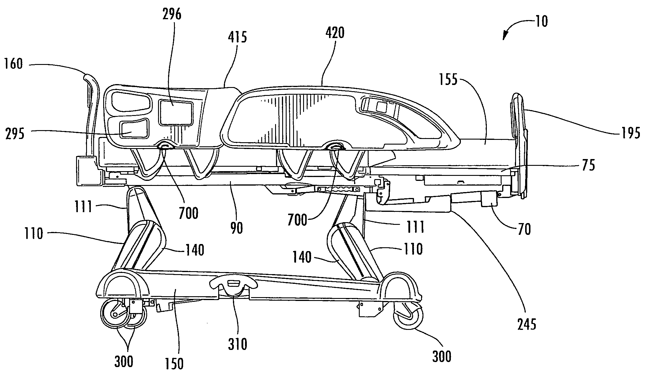
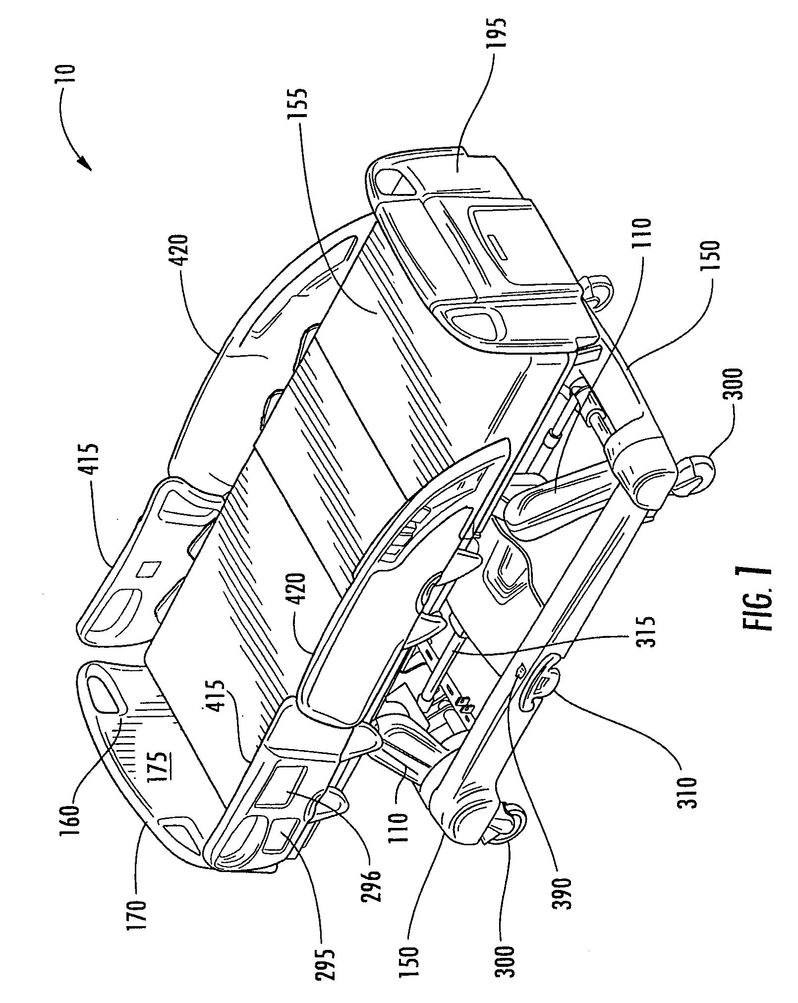
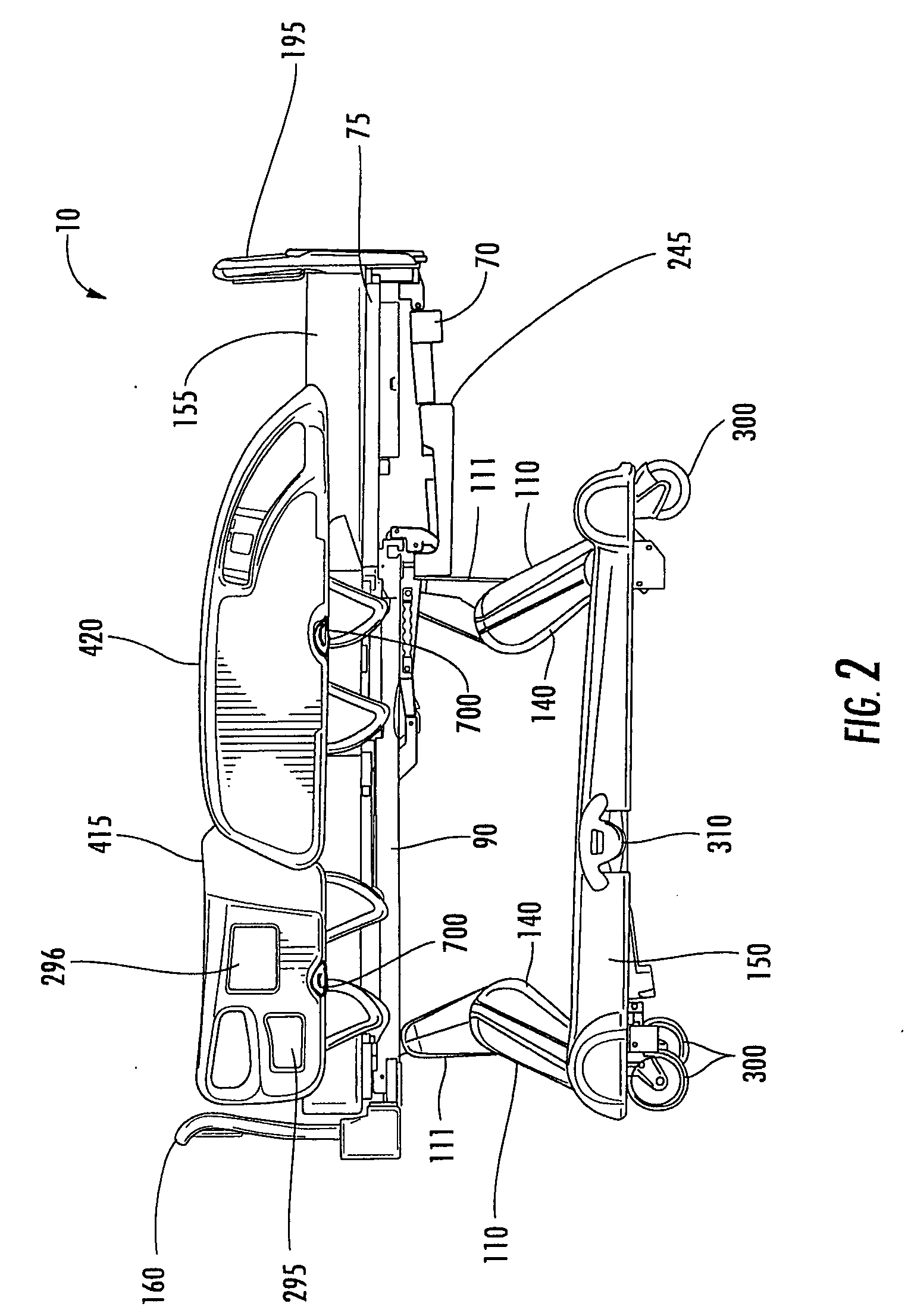
[0090] A patient support apparatus 10 according to the present disclosure is shown in FIG. 1. Patient support apparatus 10 includes a mattress or lying surface 155 upon which the patient is positioned, a frame system that supports the lying surface or other mattress 155, a pair of head-end side rails 415, a pair of foot-end side rails 420, a headboard 160, and a footboard 195. The frame system includes a deck support 20 supported by an intermediate frame 90, which is supported by an elevation system comprising lift arms 110, 111 configured to raise and low...


PUM


Abstract

A patient support apparatus may include a base frame, lift arms, an intermediate frame, a deck support having three articulating sections, a brake system, various drive motors, actuators, and sensors, at least one power source, communication devices, and at least one controller, wherein the lift arms, articulating sections, drive motors, brake system, and actuators may be controlled from the at least one controller and in response to signals received by the various sensors, while storing data internally and/or sending data to a remote location.

Description

FIELD OF THE INVENTION [0001] The present invention relates in general to the field of patient support apparatuses such as hospital beds. In particular, the invention relates to critical care patient support apparatuses with improved safety features, expanded configurability and accessible control and electronics for users. BACKGROUND OF THE INVENTION [0002] Hospital beds comprise complex mechanical and electronic components for movement, functionality and convenience. [0003] Foot brakes of prior art hospital beds are typically located on the side under the bed. There are certain disadvantages associated with such foot brakes. For example, during activation, a user such as a nurse has to hold on to the bed, balance on one foot and stretch the other foot under the bed to engage or disengage the brake. As such, if the side rail is in the lower position, visibility may be reduced. In addition, if the patient is exiting the bed, the bed may move, which may be unsafe. Furthermore, the we...

Claims


Application Information

Patent Timeline
Patent Type & Authority Applications(United States)
IPC IPC(8): A61G7/015A61G7/05A61G7/012A47C21/08
CPCA61G7/005A61G7/012A61G7/015A61G7/018A61G7/05A61G7/0507A61G2203/20A61G2007/0514A61G2007/0528A61G2203/36A61G2203/42A61G7/0506A61G2203/16A61G2007/0509A61G7/0509A61G7/0514A61G7/0528
Inventor LEMIRE, GUYDIONNE, JEAN-PAULCANTIN, NICOLASMORIN, MARCOPARE, RICHARDCASTONGUAY, PASCALPETITPAS, LUCWAN FONG, DAVID KIM SOUI
Owner STRYKER CORP
Why Eureka
Try Eureka