Tilt-up support tower

a support tower and tilt-up technology, applied in the direction of buildings, buildings, buildings, etc., can solve the problem that the tower does not have a multi-step tilt-up system, and achieve the effect of easy raising and lowering

Inactive Publication Date: 2007-08-02
G MCNEILUS
View PDF18 Cites 37 Cited by
  • Summary
  • Abstract
  • Description
  • Claims
  • Application Information

AI Technical Summary

Benefits of technology

[0007] By means of the present invention there is provided a collapsible, tilt-up and pivoting support tower assembly for supporting an elevated device of interest, such as an electric power generating wind turbine, which requires only a small, low-power operating winch to raise and lower the tower providing both ease of raising into place and lowering for disassembly or servicing of associated equipment. The support tower assembly of the invention includes an upper tower section and a tower base section pivotally joined together. In one embodiment, the assembly is based on three-point support in which the tower base section is also pivotally mounted on two legs and has a free leg to provide a third support point. Both the upper tower section and the tower base section are readily raised and lowered using separate cable systems and a mechanized winch. A mounting base system is provided which includes three spaced points of support for receiving the support legs for the base section and includes a pair of spaced pivotal mounts and a fixed leg receiving mount spaced from the pivotal mounts and providing an anchor point for the third leg.

Problems solved by technology

However, such towers do not have a multi-step tilt-up system with a leveraged construction which allows easy staged tilting for both placement and maintenance.

Method used


Image

  • Tilt-up support tower
  • Tilt-up support tower
  • Tilt-up support tower

Examples


Embodiment Construction

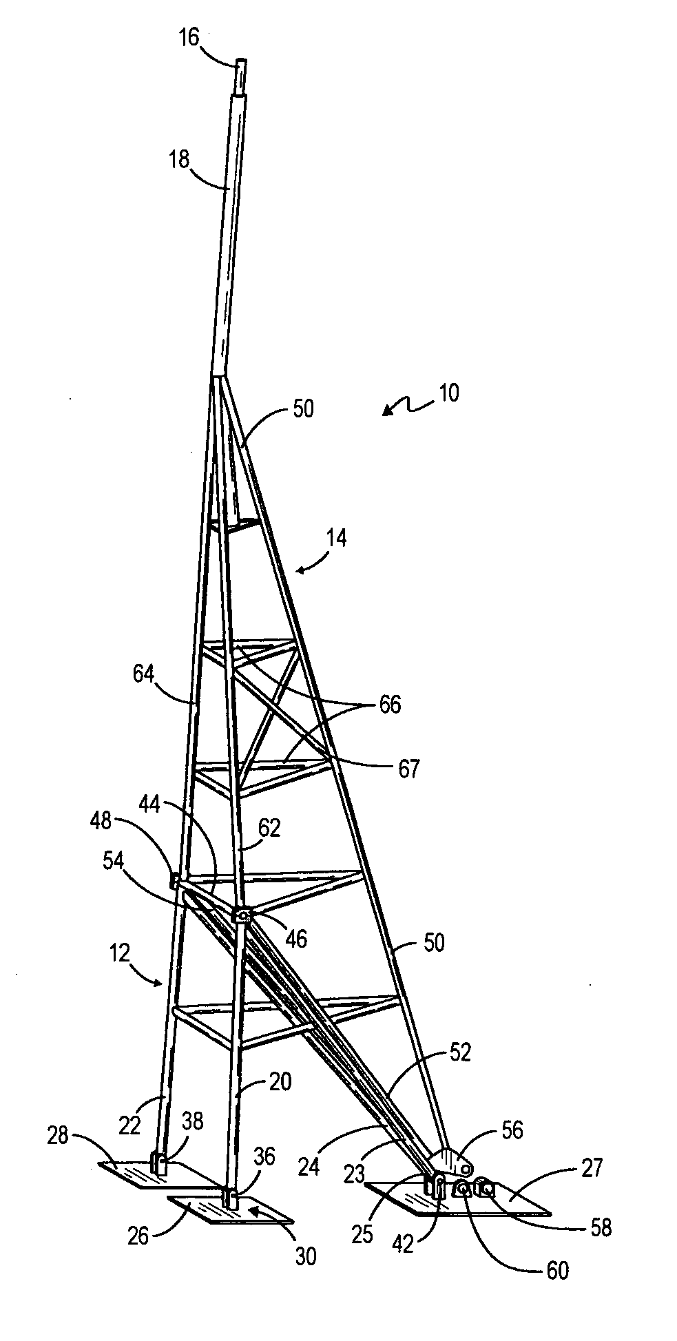
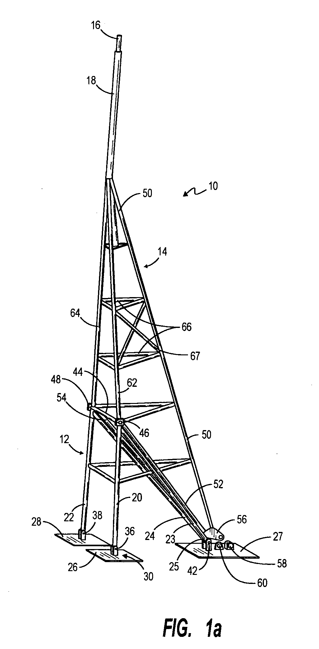
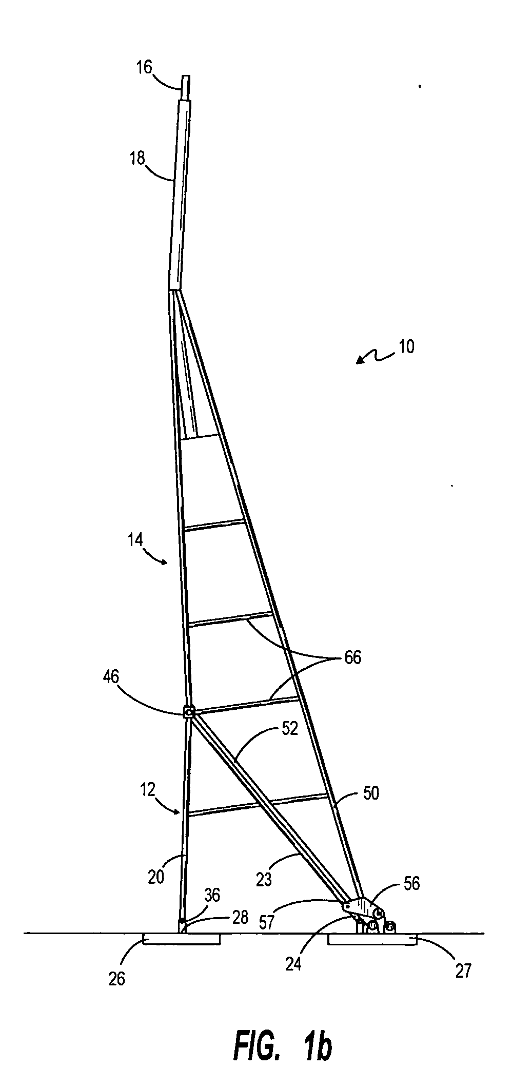
[0030] The detailed description is directed to one or more embodiments of the inventive concepts of the present invention and this material is presented as being representative of these concepts but is not intended to be interpreted as limiting with respect to any aspect of the invention. In view of the above, the embodiments of the drawings will be described. One embodiment is illustrated in FIGS. 1a-6b and alternative embodiments are shown in FIGS. 7 and 8a-12.

[0031]FIGS. 1a and 1b illustrate in schematic form perspective and side elevational views of an embodiment of a collapsible, tilt-up support tower assembly shown in the fully deployed or elevated position. The support tower assembly, generally denoted by the reference character 10, includes a lower tower section or tower base section 12 and an upper tower section 14. The upper tower section 14 carries a vertically disposed mast 16 supported from and secured to a support member or tower tube 18. Tower tube 18 and mounting po...


PUM


Abstract

The support tower assembly of the disclosed invention includes an upper tower section and a tower base section pivotally joined together. The tower base section is also pivotally mounted. Both the upper tower section and the lower base section are readily pivoted selectively to be raised and lowered using a leveraged design cable systems and a small winch. A mounting base system is provided to support the tilt-up tower.

Description

BACKGROUND OF THE INVENTION [0001] I. Field of the Invention [0002] The present invention relates generally to elevating support structures or towers. More particularly, the present invention is directed to a partially counter-balanced, multi-stage pivoting support tower assembly for supporting a conventional elevated operating device of interest, such as an electric power generating wind turbine, in which ease of raising the tower and lowering the tower to service the device of interest are advantages. [0003] II. Related Art [0004] Support towers for electric power generating wind turbine devices, radio transmitters, cellular phone relay stations, television antennae equipment and other such elevated devices have been in use for many years. These towers usually are assembled from successive sections raised by derrick cranes or the like and bolted into place by workers who have scaled the assembled portion. The device of interest is normally fixed to a mast attached to the top secti...

Claims


Application Information

Patent Timeline
Patent Type & Authority Applications(United States)
IPC IPC(8): E02D27/00
CPCE04H12/10E04H12/187E04H2012/006Y02E10/728E04H12/345
Inventor CHRISTENSON, RONALD E.
Owner G MCNEILUS
Why Eureka
Try Eureka