Self-stick metal plate and method of applying the same

a self-sticking, metal plate technology, applied in the direction of roofs, washers, constructions, etc., can solve the problems of weak points in the waterproofing system, the cost penalty of the adhesion system, and the deterioration of the mechanical fastening membrane, so as to improve the resistance to wind uplift forces, improve the durability, and prevent the effect of leaking in the roof structur

Inactive Publication Date: 2007-08-02
BUILDING MATERIALS INVESTMENT
View PDF33 Cites 55 Cited by
  • Summary
  • Abstract
  • Description
  • Claims
  • Application Information

AI Technical Summary

Benefits of technology

[0013] One object of the present invention is to provide an inexpensive mechanical fastener of improved durability and improved resistance to wind uplift forces. Yet another object of the present invention is to provide a mechanical fastener that does not penetrate the roofing membrane or roof deck in order to prevent leaking in the roof structure. Another object of the present invention is to provide an improved meth

Problems solved by technology

Adhered roof membrane retention systems suffer from the cost penalty while mechanical fasteners and related fastening systems generally require fixation to the roofing substrate via mechanical fasteners.
Although the many known variations for attaching a membrane roof to a roof deck may perform satisfactorily under certain conditions, further improvements on attaching a membrane roof to a roof deck are desired as several problems occur in the mechanical fasteners in the prior art.
Mechanically fastened membranes are

Method used


Image

  • Self-stick metal plate and method of applying the same
  • Self-stick metal plate and method of applying the same
  • Self-stick metal plate and method of applying the same

Examples


second embodiment

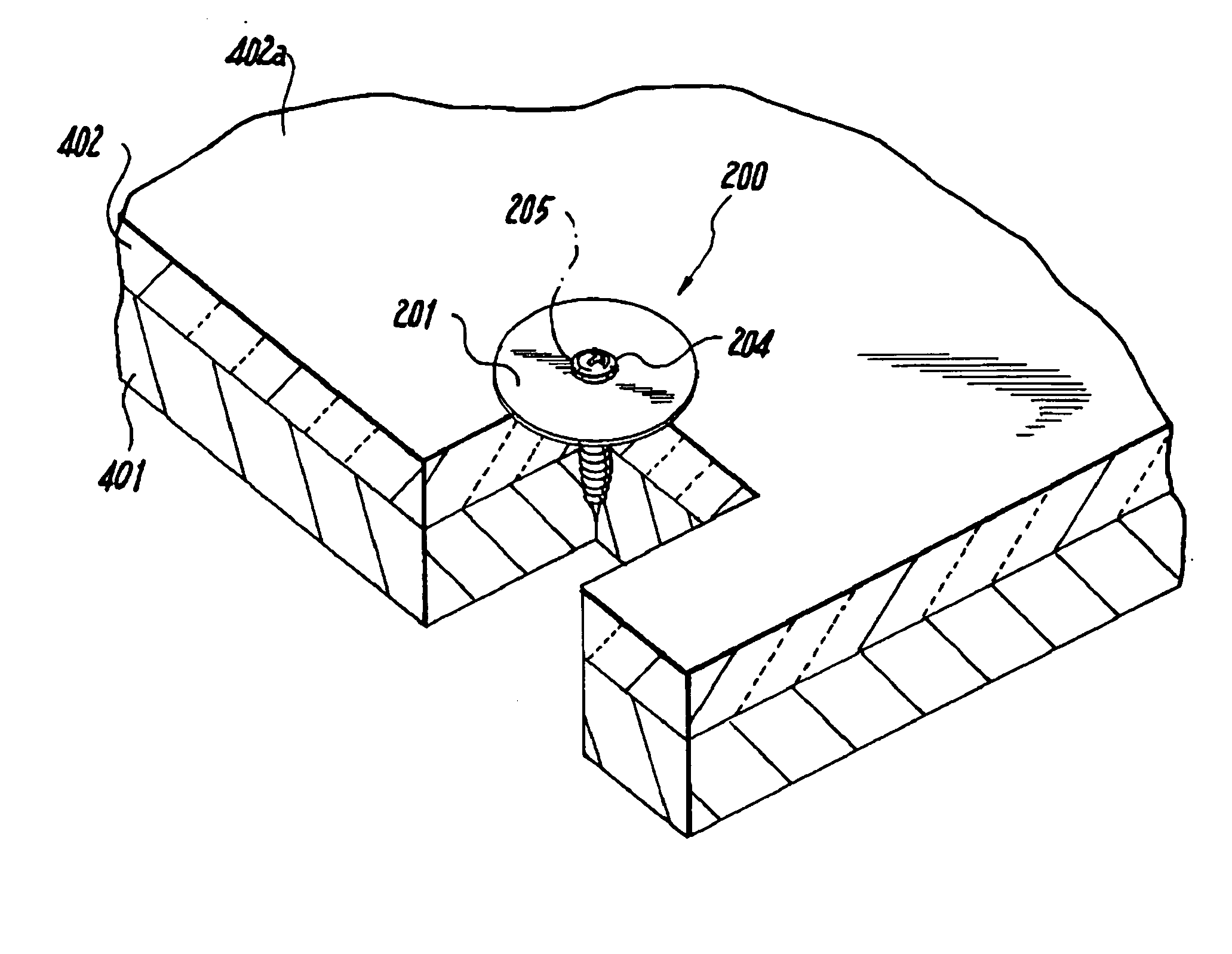
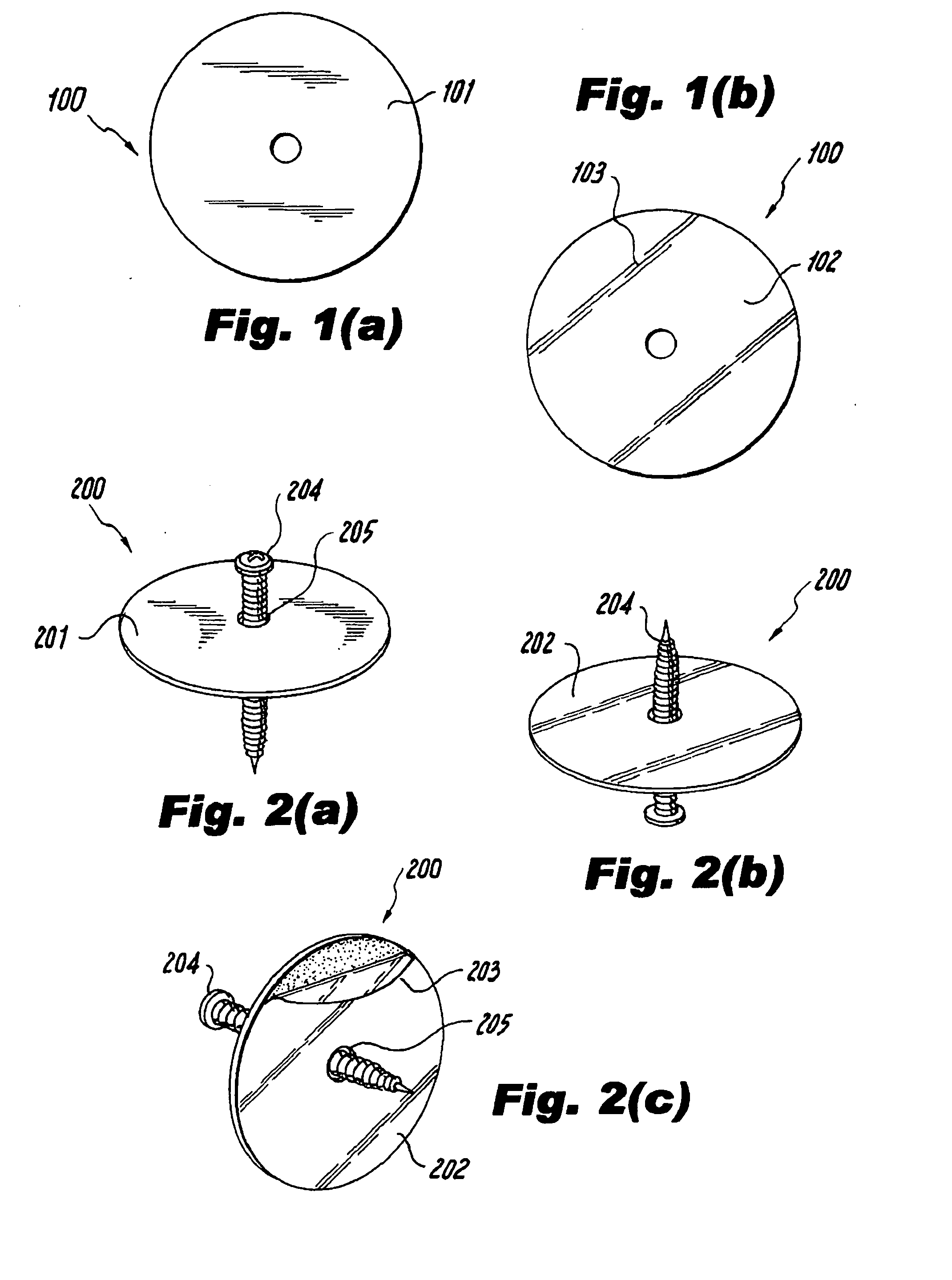
[0030]FIG. 2(a) illustrates the metal plate of the present invention having a fastener. FIG. 2(a) shows a metal plate 200 having a top side 201 which can have a coated layer. Additionally, a fastening device 204 is provided at the center 205 of the metal plate 200. Any known fastening device 204 can be used as known to one of ordinary skill in the art, such as a screw. The fastening device 204 preferably goes through the center 205 and through the entire metal plate 200 from the top side 101 extending through the bottom side 102, and screws onto the roof deck to attach the metal plate 200 to the roof deck.

[0031]FIG. 2(b) illustrates a side view of the second embodiment of the metal plate 200. FIG. 2(c) illustrates a bottom view of the second embodiment of the metal plate 200, having a bottom side 202 and a film 203 that covers the adhesive layer on the bottom side 202 of the metal plate 200. The mechanical fastener 204 penetrates through the entire metal plate 200 through the center...

first embodiment

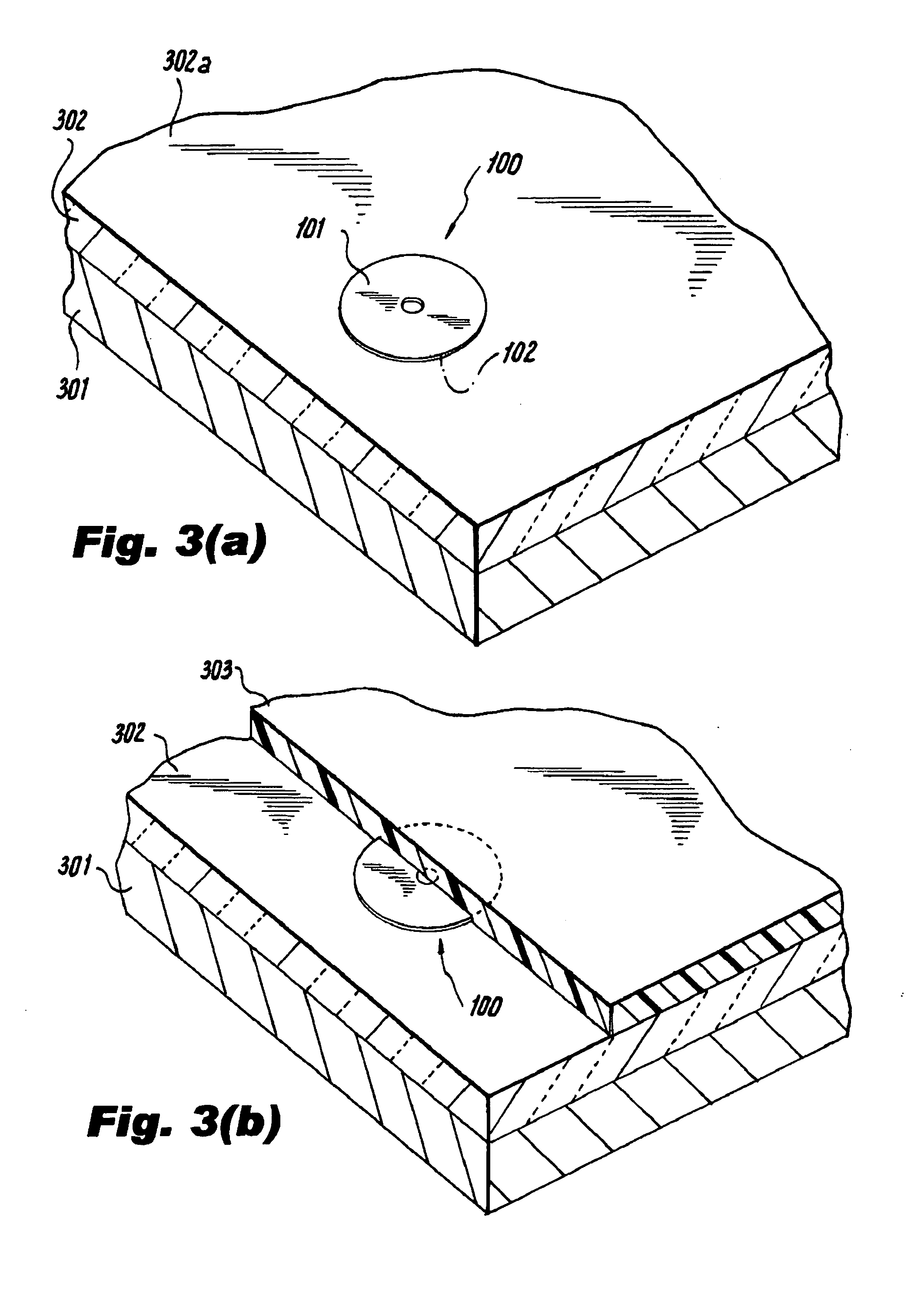
[0032] A method of application of the metal plate of the present invention is illustrated in FIGS. 3(a)-3(b). As shown in FIG. 3(a), the metal plate 100 is to be positioned upon the roof deck 301. As known in the art, insulation 302 may be applied over the roof deck 301 as desired. Examples of suitable insulation materials include polyurethane, polystyrene, wood fiberboard, polyisocyanarate and the like. Usually, at an outer perimeter of the roof deck 301 is a wall (not shown) which extends generally perpendicularly upward from the roof deck 301 above the plane of the roof deck 301.

[0033] The film 103 is then removed from the bottom side 102 of the metal plate 100, and the bottom side 102 is attached to the top surface 302a of the insulation 302. The adhesive layer on the bottom side 102 of the metal plate 100 attaches the metal plate 100 to the insulation 302, or roof deck 301 if insulation 302 is not used. The top side 101 has a coated layer, as described earlier.

[0034] As shown ...


PUM


Abstract

A coated metal plate is provided as a mechanical fastening device for a roof deck. The top side of the metal plate can have a coated layer, and the bottom side of the metal plate has an adhesive layer. The adhesive layer is covered by a film, which is removable and can be peeled off at the time of installation. The bottom side of the metal plate is attached to the roof deck by the adhesive layer, and a roofing membrane is heat welded to the coated top side of the metal plate. The disc shaped metal plate can have a hole in the center of the plate, and a fastening device such as a screw can extend through the hole and attach the metal plate to the roof deck for additional support.

Description

BACKGROUND OF THE INVENTION [0001] 1. Field of the Invention [0002] The present invention relates generally to mechanical fasteners, and more specifically, to a peel and stick type of coated mechanical fastener that secures a flexible sheet or membrane to the roof without penetrating the membrane and to a method of applying the same. [0003] 2. Prior Art [0004] A roofing system generally includes a roof deck which is considered the structural supporting surface of a building extending between the surrounding exterior walls of the building. The roof deck may be constructed from plywood, metal decking or concrete or any other suitable material. Depending upon the construction, the roof deck may extend over the surrounding exterior walls or the roof deck may stop short of the exterior walls thereby forming a parapet wall, i.e., a low retaining wall at the edge of the roof deck. If desired, the roofing system may also include an insulation barrier formed from polyisocyanarate or any othe...

Claims


Application Information

Patent Timeline
IPC IPC(8): E04B1/00
CPCE04D5/143E04D5/145F16B43/00E04D5/148E04D5/147
Inventor SHAH, VIJAY G.
Owner BUILDING MATERIALS INVESTMENT
Why Eureka
Try Eureka