Fuel injector isolation seat

a technology of fuel injector and isolation seat, which is applied in the direction of fuel injection apparatus, machine/engine, feed system, etc., can solve the problems of noise-emitting vibration, and achieve the effect of reducing the transmission of noise-producing vibration and high frequency

Active Publication Date: 2007-08-02
GM GLOBAL TECH OPERATIONS LLC
View PDF21 Cites 47 Cited by
  • Summary
  • Abstract
  • Description
  • Claims
  • Application Information

AI Technical Summary

Benefits of technology

[0005] Accordingly, the isolated fuel delivery system of the present invention reduces the transmission of noise producing, high frequency vibrations from the fuel injector to the engine.

Problems solved by technology

The sequential energization of the fuel injectors may operate to induce pressure pulsations within the fuel rail, which may produce noise-emitting vibrations.

Method used


Image

  • Fuel injector isolation seat
  • Fuel injector isolation seat

Examples


Embodiment Construction

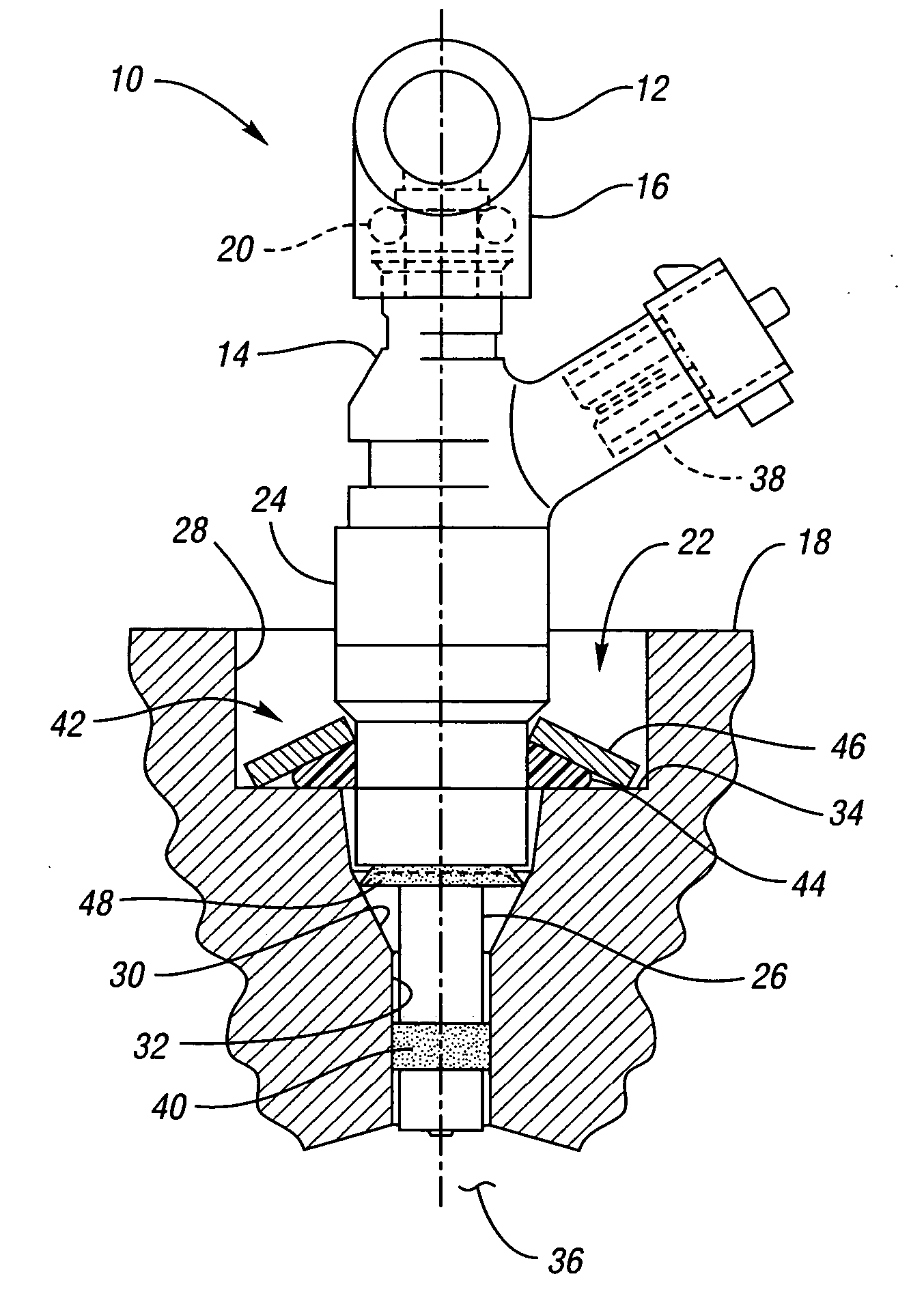
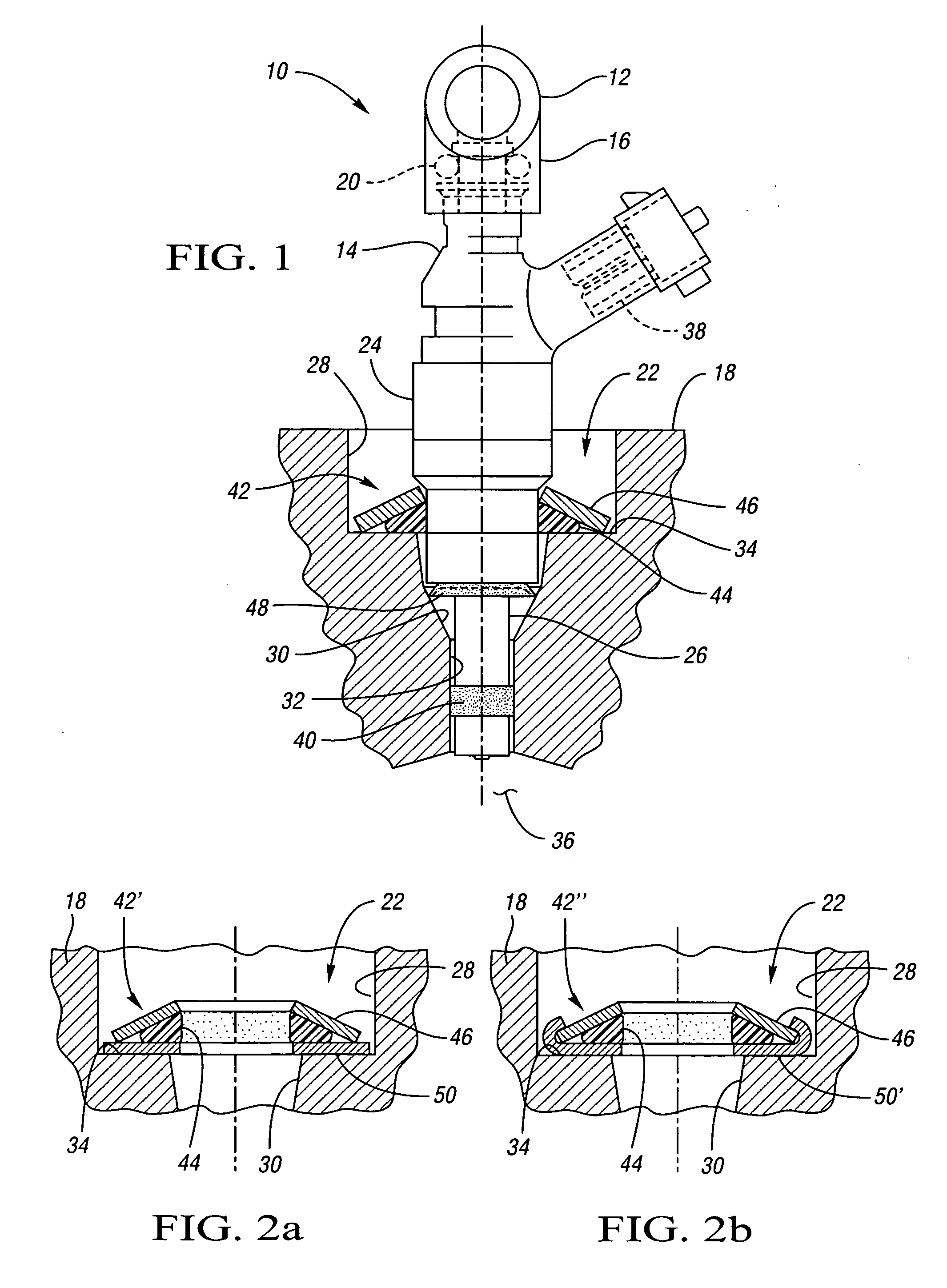
[0013] Referring to the drawings wherein like reference numbers represent like components throughout the several figures, there is shown in FIG. 1 an isolated fuel delivery system 10 having a fuel rail 12 and a direct injection fuel injector 14. The fuel rail 12 operates as a conduit to communicate pressurized fuel to the fuel injector 14. In the preferred embodiment, the fuel rail 12 will be isolated at its point of attachment. Although only one fuel injector 14 is shown in FIG. 1, those skilled in the art will recognize that the fuel rail 12 may operate as a manifold to provide multiple fuel injectors 14 with pressurized fuel. A fuel injector boss 16 operates to retain one end of the fuel injector 14 with respect to the fuel rail 12, while another end of the fuel injector 14 is disposed within a cylinder head 18 of an engine, not shown. The fuel injector 14 includes an injector seal 20, which operates to contain pressurized fuel within the fuel rail 12.

[0014] The cylinder head 18...


PUM


Abstract

An isolation seat assembly for a fuel injector that is at least partially disposed within a stepped bore defined by a cylinder head, the stepped bore includes a land. The isolation seat assembly includes a cupped spring washer and an elastomeric ring member disposed between the cupped spring washer and the land. The isolation seat assembly operates to bias the fuel injector away from the land to substantially isolate the fuel injector from the head. The cupped spring washer and elastomeric ring member may be bonded to one another. Additionally, the isolation seat assembly may include a washer member between the elastomeric ring member and the land. The washer member operates to distribute axial forces from the fuel injector to the land. At least a portion of the washer member may be crimped into engagement with the cupped spring washer, thereby capturing the elastomeric ring member therein between.

Description

TECHNICAL FIELD [0001] The present invention relates to fuel delivery systems for internal combustion engines. BACKGROUND OF THE INVENTION [0002] Fuel delivery systems for internal combustion engines are available in many different varieties, one of the more common of which is the port fuel injection system. The port fuel injection system utilizes a plurality of fuel injectors each of which delivers a predetermined amount of fuel to the inlet port of an associated combustion chamber. In such systems, the fuel injectors are mounted in sockets or injector bosses of a manifold or fuel rail, which operates to communicate fuel to each of the injectors. [0003] Recent advances in fuel delivery and combustion research has allowed direct injection, or DI, fuel delivery systems to increase in popularity. The DI fuel delivery system provides a fuel injector within a cylinder head of the internal combustion engine. The DI fuel injector operates to inject a predetermined amount of fuel directly ...

Claims


Application Information

Patent Timeline
Patent Type & Authority Applications(United States)
IPC IPC(8): F02M61/14
CPCF02M2200/858F02M61/14
Inventor BEARDMORE, JOHN M.
Owner GM GLOBAL TECH OPERATIONS LLC
Why Eureka
Try Eureka